MPXV5004DP Freescale Semiconductor, MPXV5004DP Datasheet - Page 4
MPXV5004DP
Manufacturer Part Number
MPXV5004DP
Description
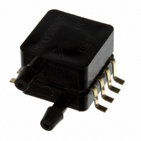
SENSOR PRESSURE SMD 8-SOP
Manufacturer
Freescale Semiconductor
Series
MPXV5004r
Datasheet
1.MPXV5004GC6T1.pdf
(22 pages)
Specifications of MPXV5004DP
Pressure Type
Differential
Operating Pressure
0.57 PSI, 3.92 kPa
Port Size
Male, 0.13" (3.302mm) Tube, Dual
Output
0 ~ 4.9V
Voltage - Supply
4.75 V ~ 5.25 V
Termination Style
PCB
Operating Temperature
0°C ~ 85°C
Package / Case
8-SOP Dual Port
Accuracy
1.5 %
Mounting Style
SMD/SMT
Maximum Operating Temperature
+ 85 C
Minimum Operating Temperature
0 C
Operating Supply Voltage
5 V
Supply Voltage (min)
4.75 V
Supply Voltage (max)
5.25 V
Supply Current
10 mA
Output Voltage
4.9 V
Shutdown
No
Operating Pressure Range
0 To 3.92kPa
Connection Size
3.302mm
Sensitivity, V/p
1V/kPa
Sensor Case Style
SOP
No. Of Pins
8
Rohs Compliant
Yes
Lead Free Status / RoHS Status
Lead free / RoHS Compliant
Available stocks
Company
Part Number
Manufacturer
Quantity
Price
Company:

Part Number:
MPXV5004DP
Manufacturer:
FREESCALE
Quantity:
65
Part Number:
MPXV5004DP
Manufacturer:
FREESCALE
Quantity:
20 000


MPXV5004G
4
Maximum Ratings
Table 2. Maximum Ratings
On-chip Temperature Compensation and Calibration
integrating the shear-stress strain gauge, temperature
compensation, calibration and signal conditioning circuitry
onto a single monolithic chip.
chip carrier (Case 482). A fluorosilicone gel isolates the die
surface and wire bonds from the environment, while allowing
the pressure signal to be transmitted to the silicon diaphragm.
are based on use of dry air as pressure media. Media, other
than dry air, may have adverse effects on sensor
performance and long-term reliability. Internal reliability and
Maximum Pressure (P1 > P2)
Storage Temperature
Operating Temperature
1. Exposure beyond the specified limits may cause permanent damage or degradation to the device.
Figure 1
The performance over temperature is achieved by
Figure 2
The MPxx5004G series sensor operating characteristics
Pressure
shows a block diagram of the internal circuitry integrated on a pressure sensor chip.
illustrates the gauge configuration in the basic
Rating
(1)
Lead Frame
Sensing
Element
Wire Bond
Figure 2. Cross-Sectional Diagram (Not to Scale)
Figure 1. Integrated Pressure Sensor Schematic
Differential Sensing Element
Fluorosilicone
GND
Gel Die Coat
3
and Calibration
Compensation
Temperature
Thin Film
Circuitry
Pins 1, 5, 6, 7, and 8 are NO CONNECTS
for small outline package device.
V
S
2
P1
P2
qualification test for dry air, and other media, are available
from the factory. Contact the factory for information regarding
media tolerance in your application.
interfacing the output of the MPxx5004G to the A/D input of
the microprocessor or microcontroller. Proper decoupling of
the power supply is recommended.
for operation over a temperature range of 10°C to 60°C using
the decoupling circuit shown in
saturate outside of the specified pressure range.
Die
Symbol
Figure 3
Typical, minimum and maximum output curves are shown
P
T
T
MAX
STG
Gain Stage #2
Shift Circuitry
A
Reference
Ground
and
shows the recommended decoupling circuit for
Steel Cap
Stainless
Die Bond
Thermoplastic
Case
4
–30 to +100
0 to +85
V
Value
OUT
16
Figure
Freescale Semiconductor
3. The output will
Unit
kPa
°C
°C
Sensors
Related parts for MPXV5004DP
Image
Part Number
Description
Manufacturer
Datasheet
Request
R

Part Number:
Description:
Manufacturer:
Freescale Semiconductor, Inc
Datasheet:
Part Number:
Description:
Manufacturer:
Freescale Semiconductor, Inc
Datasheet:
Part Number:
Description:
Manufacturer:
Freescale Semiconductor, Inc
Datasheet:
Part Number:
Description:
Manufacturer:
Freescale Semiconductor, Inc
Datasheet:
Part Number:
Description:
Manufacturer:
Freescale Semiconductor, Inc
Datasheet:
Part Number:
Description:
Manufacturer:
Freescale Semiconductor, Inc
Datasheet:
Part Number:
Description:
Manufacturer:
Freescale Semiconductor, Inc
Datasheet:
Part Number:
Description:
Manufacturer:
Freescale Semiconductor, Inc
Datasheet:
Part Number:
Description:
Manufacturer:
Freescale Semiconductor, Inc
Datasheet:
Part Number:
Description:
Manufacturer:
Freescale Semiconductor, Inc
Datasheet:
Part Number:
Description:
Manufacturer:
Freescale Semiconductor, Inc
Datasheet:
Part Number:
Description:
Manufacturer:
Freescale Semiconductor, Inc
Datasheet:
Part Number:
Description:
Manufacturer:
Freescale Semiconductor, Inc
Datasheet:
Part Number:
Description:
Manufacturer:
Freescale Semiconductor, Inc
Datasheet:
Part Number:
Description:
Manufacturer:
Freescale Semiconductor, Inc
Datasheet: