RPI-352 Rohm Semiconductor, RPI-352 Datasheet
RPI-352
Manufacturer Part Number
RPI-352
Description
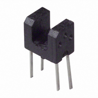
SENSOR OPTO SLOT 3MM TRANS THRU
Manufacturer
Rohm Semiconductor
Type
Unamplifiedr
Datasheet
1.RPI-352.pdf
(2 pages)
Specifications of RPI-352
Sensing Distance
0.118" (3mm)
Sensing Method
Transmissive
Output Configuration
Phototransistor
Current - Dc Forward (if)
50mA
Current - Collector (ic) (max)
30mA
Voltage - Collector Emitter Breakdown (max)
30V
Response Time
10µs, 10µs
Mounting Type
Through Hole
Package / Case
PCB Mount
Operating Temperature
-25°C ~ 85°C
Operating Temperature Range
-25°C To +85°C
Digital Ic Case Style
RPI-352
No. Of Pins
4
Svhc
No SVHC (18-Jun-2010)
Operating Temperature Max
85°C
Operating Temperature Min
-25°C
Package /
RoHS Compliant
Output Collector Emitter Voltage (detector)
30 V
Maximum Reverse Voltage (emitter)
5 V
Maximum Collector Current (detector)
30 mA
Slot Width
3 mm
Output Device
Phototransistor
Power Dissipation
80 mW
Maximum Fall Time
10000 ns (Typ)
Maximum Operating Temperature
+ 85 C
Maximum Rise Time
10000 ns (Typ)
Minimum Operating Temperature
- 25 C
Wavelength
950 nm
Ic Function
Photo Interrupter
Rohs Compliant
Yes
Base Number
352
Lead Free Status / RoHS Status
Lead free / RoHS Compliant
Lead Free Status / RoHS Status
Lead free / RoHS Compliant
Other names
511-1351
RPI-352
RPI-352
Available stocks
Company
Part Number
Manufacturer
Quantity
Price
Company:

Part Number:
RPI-352
Manufacturer:
ROHM Semiconductor
Quantity:
510
Company:
Part Number:
RPI-352
Manufacturer:
KODENSHI
Quantity:
100
Part Number:
RPI-352
Manufacturer:
ROHM/罗姆
Quantity:
20 000
Company:
Part Number:
RPI-352C
Manufacturer:
ROHM
Quantity:
585


RPI-352
Absolute maximum ratings (Ta=25°C)
Electrical and optical characteristics (Ta=25°C)
Electrical and optical characteristics curves
Forward current
Reverse voltage
Power dissipation
Collector-emitter voltage
Emitter-collector voltage
Collector current
Collector power dissipation
Operating temperature
Storage temperature
Forward voltage
Reverse current
Dark current
Peak sensitivity wavelength
Collector current
Collector-emitter saturation
voltage
Response time
Cut-off frequency
Peak light emitting wavelength
Response time
Maximum sensitivity wavelength
100
100
75
50
25
Parameter
75
50
25
Parameter
0
0
Fig.1 Relative output current vs.
Fig.4 Relative output current vs.
0
0
0.5
0.5
distance ( )
distance ( )
DISTANCE : d (mm)
DISTANCE : d (mm)
1.0
1.0
d
1.5
1.5
2.0
2.0
Symbol
V
I
CE(sat)
tr tf
2.5
2.5
V
CEO
λ
tr tf
I
I
f
λ
Symbol
λ
R
C
C
F
P
P
P
V
V
Topr
Tstg
V
P
P
I
CEO
ECO
I
F
C
R
D
C
3.0
3.0
Photointerrupter, Small type
Min.
0.2
−
−
−
−
−
−
−
−
−
−
−25 to +85
−30 to +85
Typ.
800
950
1.3
1.0
800
10
10
−
−
−
1
Limits
4.5
50
80
30
30
80
5
Fig.5 Power dissipation / collector power
120
100
20
Max.
50
40
30
20
10
80
60
40
0
0
1.6
10
0.5
0.4
−
−
−
−
−
−
−
−20
−20
dissipation vs. ambient temperature
Fig.2 Forward current falloff
AMBIENT TEMPERATURE : Ta (°C)
AMBIENT TEMPERATURE : Ta (°C)
P
D
Unit
MHz
µA
µA
nm
mA
µs
nm
nm
0
V
V
µs
0
P
Unit
mW
mW
C
mA
mA
°C
°C
V
V
V
20
20
I
V
V
V
I
V
I
∗ Non-coherent Infrared light emitting diode used.
V
∗ This product is not designed to be protected against electromagnetic wave.
F
F
F
= 50mA
CC
= 50mA
R
CE
CE
= 20mA, I
CC
= 5V
= 5V, I
= 10V
= 5V, I
= 5V, I
40
40
C
F
F
= 1mA, R
= 20mA
60
60
C
= 20mA, R
= 0.1mA
80
80
L
= 100Ω
L
= 100Ω
100
100
Conditions
−
−
Floppy disk drives
Printers
Facsimiles
VCR
1) Positioning pin enables precision
2) Gap between emitter and detector
3) Compact
Applications
Features
mounting.
is 3.0mm.
100
50
40
30
20
10
50
0
0
0
Fig.3 Forward current vs. forward
Fig.6 Relative output vs. ambient
−25
AMBIENT TEMPERATURE : Ta (°C)
FORWARD VOLTAGE : V
0.4
temperature
voltage
0
0.8
25
1.2
50
−25°C
F
1.6
25°C
50°C
75°C
(
V
75
0°C
)
2.0
100
2.0
1.6
1.2
0.8
0.4
2.5
1.5
0.5
0
2
1
0
COLLECTOR TO EMITTER VOLTAGE : V
0
0
External dimensions (Unit : mm)
Fig.10 Output characteristics
Fig.7 Collector current vs.
10
FORWARD CURRENT : I
2
forward current
0.3
I
F
=50mA
20
40mA
30mA
20mA
10mA
4
+0
φ 1
-0.1
+0
-0.1
+0
-0.1
30
6
Gap
F
40
(mA)
6.4 ± 0.2
8
3 ± 0.2
V
CE
(5)
=5V
CE
50
10
(V)
A
A
4-0.2
2-R1
Fig.11 Response time measurement circuit
t
t
t
d
r
1000
f
100
:
:
:
Optical axis center
10
Input
1
0.1
Delay time
Rise time (time for output current to rise
from 10% to 90% of peak current)
Fall time (time for output current to fall
from 90% to 10% of peak current)
COLLECTOR CURRENT : Ic (mA)
Fig.8 Response time vs.
V
CC
R
L
collector current
Output
1
Output
Input
Cross-section A-A
t
d
Cathode
4-0.5
Anode
10
t
r
0.4
R
R
R
Ta=25°C
V
L
L
L
=1kΩ
=500Ω
=100Ω
CC
(2.5)
=5V
t
f
Through hole
10%
100
90%
Collector
Emitter
4- φ 0.8
C0.7
φ 1
1000
Notes:
1.
2. Dimension in parenthesis are
100
0.1
10
shall be ±0.2 .
show for reference.
1
Unspecified tolerance
−25
AMBIENT TEMPERATURE : Ta (°C)
Fig.9 Dark current vs.
5
0
ambient temperature
25
φ 1.4
50
V
V
V
CE
CE
CE
75
=10V
=20V
=30V
100
Related parts for RPI-352
Image
Part Number
Description
Manufacturer
Datasheet
Request
R

Part Number:
Description:
SENSOR OPTICAL SLOTTED 1.1MM
Manufacturer:
Rohm Semiconductor
Datasheet:

Part Number:
Description:
SENS OPTO SLOT 3MM TRANS SNAP-IN
Manufacturer:
Rohm Semiconductor
Datasheet:

Part Number:
Description:
SENSOR OPTO SLOT 1.2MM TRANS SMD
Manufacturer:
Rohm Semiconductor
Datasheet:


Part Number:
Description:
SENSOR OPTO SLOT 1.2MM TRANS SMD
Manufacturer:
Rohm Semiconductor
Datasheet:

Part Number:
Description:
SENSOR OPTO TRANS IMM REFL SMD
Manufacturer:
Rohm Semiconductor
Datasheet:

Part Number:
Description:
SENSR OPTO SLOT 2.3MM TRANS THRU
Manufacturer:
Rohm Semiconductor
Datasheet:

Part Number:
Description:
PHOTOINTERRUPTER SLOT 5MM PCB
Manufacturer:
Rohm Semiconductor
Datasheet:

Part Number:
Description:
SENSOR OPTO SLOT 1MM TRANS THRU
Manufacturer:
Rohm Semiconductor
Datasheet:
Part Number:
Description:
SENSR OPTO SLOT 0.8MM TRANS THRU
Manufacturer:
Rohm Semiconductor
Datasheet:
Part Number:
Description:
SENSOR OPTO SLOT 1.2MM TRANS SMD
Manufacturer:
Rohm Semiconductor
Datasheet:
Part Number:
Description:
SENSOR OPTO SLOT 1.2MM TRANS SMD
Manufacturer:
Rohm Semiconductor
Datasheet:
Part Number:
Description:
SENSOR OPTO TRANS IMM REFL SMD
Manufacturer:
Rohm Semiconductor
Datasheet:
RPI-352 Summary of contents
Page 1
... RPI-352 Photointerrupter, Small type Absolute maximum ratings (Ta=25°C) Parameter Symbol Limits Unit Forward current Reverse voltage Power dissipation Collector-emitter voltage CEO Emitter-collector voltage V 4.5 V ECO Collector current Collector power dissipation −25 to +85 °C Operating temperature Topr −30 to +85 °C Storage temperature Tstg Electrical and optical characteristics (Ta=25° ...
Page 2
Appendix No technical content pages of this document may be reproduced in any form or transmitted by any means without prior permission of ROHM CO.,LTD. The contents described herein are subject to change without notice. The specifications for the product ...