E3Z-G61-M3J Omron, E3Z-G61-M3J Datasheet - Page 3
E3Z-G61-M3J
Manufacturer Part Number
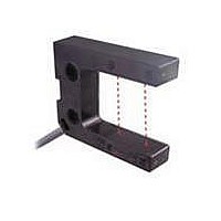
E3Z-G61-M3J
Description
1 AXIS NPN PIGTAIL W/M8 CONN
Manufacturer
Omron
Series
E3Z-Gr
Type
Photoelectric Sensorr
Specifications of E3Z-G61-M3J
Sensing Distance
0.984" (25mm)
Sensing Method
Through-Beam
Output Configuration
NPN - Dark-ON/Light-ON - Selectable
Mounting Type
Bracket Mount
Current - Supply
25mA
Voltage - Supply
12 V ~ 24 V
Response Time
1ms
Package / Case
Module, Connector
Features
Light ON / Dark ON
Height
11 mm
Length
50 mm
Maximum Operating Temperature
+ 55 C
Minimum Operating Temperature
- 25 C
Operating Supply Voltage
12 V to 24 V
Width
40 mm
Lead Free Status / RoHS Status
Lead free / RoHS Compliant
Lead Free Status / RoHS Status
Lead free / RoHS Compliant, Lead free / RoHS Compliant
Other names
E3ZG61M3J


I/O Circuit Diagrams
NPN Output
PNP Output
1 axis
E3Z-G61
E3Z-G61-M3J
2 axes
E3Z-G62
E3Z-G62-M3J
1 axis
E3Z-G81
E3Z-G81-M3J
2 axes
E3Z-G82
E3Z-G82-M3J
No. of optical
No. of optical
axes/model
axes/model
Operation
Operation
Light-ON
Dark-ON
Light-ON
Dark-ON
Light-ON
Dark-ON
Light-ON
Dark-ON
mode
mode
Control output
Output transistor
Control output
Output transistor
Operation
indicator
(orange)
Operation
indicator
(orange)
Load
(e.g., relay)
Control output
Output transistor
Load
(e.g., relay)
Control output
Output transistor
Operation
indicator
(orange)
Load
(e.g., relay)
Control output
Output transistor
Load
(e.g., relay)
Control output
Output transistor
Operation
indicator
(orange)
Load
(e.g., relay)
Operation
indicator
(orange)
Load
(e.g., relay)
Operation
indicator
(orange)
Control output
Output transistor
Operation
indicator
(orange)
Control output
Output transistor
Operation
indicator
(orange)
Load
(e.g., relay)
Load
(e.g., relay)
No incident light
No incident light
No incident light
No incident light
Timing charts
No incident light
No incident light
Timing charts
No incident light
No incident light
(Between blue and black leads)
Incident light
(Between blue and black leads)
Incident light
Incident light
(Between brown and black leads)
Incident light
Incident light
Incident light
Incident light
(Between brown and black leads)
Incident light
Operate
Operate
Operate
Operate
Operate
Operate
Operate
Operate
Reset
Reset
Reset
Reset
Reset
OFF
OFF
OFF
OFF
Reset
Reset
OFF
OFF
Reset
ON
ON
OFF
OFF
ON
ON
ON
ON
OFF
OFF
(Between brown
and black (white) leads)
OFF
OFF
(Between brown
and black (white) leads)
OFF
OFF
OFF
OFF
ON
ON
ON
ON
ON
ON
ON
ON
ON
ON
(Between blue and
black (white) leads)
(Between blue and
black (white) leads)
(LIGHT ON)
(LIGHT ON)
(LIGHT ON)
(LIGHT ON)
(DARK ON)
(DARK ON)
(DARK ON)
(DARK ON)
Operation
Operation
selector
selector
D side
D side
D side
D side
L side
L side
L side
L side
Operation
indicator
S1
(orange)
Operation
indicator
(orange)
Operation
indicator
(orange)
Operation
indicator
S1
(orange)
Connector Pin Arrangement
Connector Pin Arrangement
Pin 2 is not used.
Operation
indicator
S2
(orange)
Operation indicator
S2
(orange)
Photo-
electric
Sensor
Main
Circuit
Photo-
electric
Sensor
Main
Circuit
Photo-
electric
Sensor
Main
Circuit
1
1
Photo-
electric
Sensor
Main
Circuit
2
2
4
(Control output)
4
(Control output)
3
3
(Control output)
(Control output)
Output circuit
Output circuit
Z
D
Z
(Control
output)
D
(Control
output)
(S1)
Z
e-CON Connector Pin Arrangement
Z
e-CON Connector Pin Arrangement
D
D
Z
Z
D
1
4
2
3
1
4
3
D
Connector Pin Arrangement
Black
Brown
White
1
2
4
3
Brown
Black
Blue
Blue
1
4
3
(S1)
Connector Pin Arrangement
100mA
max.
Brown
Black
Brown
White
Black
Blue
Blue
100mA
max.
(S2)
100mA
max.
Pin 2 is not used.
1
2
3
4
1
2
3
4
100mA
max.
100mA
max.
(relay)
Load
(relay)
Load
1
(relay)
Load
1
2
2
(relay)
Load
(relay)
Load
4
4
(relay)
Load
3
3
12 to 24 VDC
0V
E3Z-G
0 V
0 V
12 to 24 VDC
12 to 24 VDC
0 V
12 to 24 VDC
3
Related parts for E3Z-G61-M3J
Image
Part Number
Description
Manufacturer
Datasheet
Request
R

Part Number:
Description:
1 AXIS NPN PRE-WIRED
Manufacturer:
Omron
Datasheet:

Part Number:
Description:
Photoelectric Sensors - Industrial E3Z-R81 IN BULK PACK (100 MIN.)
Manufacturer:
Omron
Datasheet:

Part Number:
Description:
EMITTER ONLY FOR E3Z-T61
Manufacturer:
Omron
Datasheet:
Part Number:
Description:
1 AXIS PNP PREWIRED
Manufacturer:
Omron
Datasheet:
Part Number:
Description:
1 AXIS PNP PIGTAIL W/M8 CONN
Manufacturer:
Omron
Datasheet:
Part Number:
Description:
SENSOR PHOTO AMP THRU-BEAM PNP
Manufacturer:
Omron
Datasheet:
Part Number:
Description:
THRU-BEAM NPN CONN
Manufacturer:
Omron
Datasheet:
Part Number:
Description:
30M T/B NPN 4 PIN M8 CONN
Manufacturer:
Omron
Datasheet:
Part Number:
Description:
30M T/B PNP 4 PIN M8 CONN
Manufacturer:
Omron
Datasheet:

Part Number:
Description:
G6S-2GLow Signal Relay
Manufacturer:
Omron Corporation
Datasheet:
Part Number:
Description:
Compact, Low-cost, SSR Switching 5 to 20 A
Manufacturer:
Omron Corporation
Datasheet:
Part Number:
Description:
Manufacturer:
Omron Corporation
Datasheet: