E3S-CT11 Omron, E3S-CT11 Datasheet - Page 5
E3S-CT11
Manufacturer Part Number
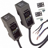
E3S-CT11
Description
SENSOR PHOTO HORZ 98' THRUBEAM
Manufacturer
Omron
Series
E3S-Cr
Type
Long Range Metal Body Sensorr
Specifications of E3S-CT11
Sensing Distance
1181.102" (30m)
Sensing Method
Through-Beam
Output Configuration
PNP - Dark-ON/Light-ON - Selectable
Mounting Type
Bracket Mount, Horizontal
Current - Supply
50mA
Voltage - Supply
10 V ~ 30 V
Response Time
1ms
Package / Case
Module, Pre-Wired
Features
Mutual interference protection
Height
29.5 mm
Length
50 mm
Maximum Operating Temperature
+ 55 C
Minimum Operating Temperature
- 25 C
Operating Supply Voltage
10 V to 30 V
Width
40.4 mm
Light Source
Infrared LED
Connection
Prewired Cable
Output Current
100mA
Supply Voltage Range Dc
10V To 30V
Sensor Housing
Rectangular
Sensor Input
Optical
Sensing Range Max
30m
Switch Terminals
Wire Leaded
Lead Free Status / RoHS Status
Contains lead / RoHS compliant by exemption
Lead Free Status / RoHS Status
Lead free / RoHS Compliant, Contains lead / RoHS compliant by exemption
Other names
E3SCT11
Z1102
Z1102
Available stocks
Company
Part Number
Manufacturer
Quantity
Price
Company:

Part Number:
E3S-CT11
Manufacturer:
OMRON
Quantity:
264
Company:
Part Number:
E3S-CT11-D
Manufacturer:
OMRON
Quantity:
475
Company:
Part Number:
E3S-CT11-L
Manufacturer:
XG
Quantity:
11 700


I/O Circuit Diagrams
NPN Output
PNP Output
Plug (Sensor I/O Connector)
E3S-CT11(-M1J)
E3S-CT61(-M1J)
E3S-CR11(-M1J)
E3S-CR61(-M1J)
E3S-CD11(-M1J)
E3S-CD12(-M1J)
E3S-CD61(-M1J)
E3S-CD62(-M1J)
E3S-CT11(-M1J)
E3S-CT61(-M1J)
E3S-CR11(-M1J)
E3S-CR61(-M1J)
E3S-CD11(-M1J)
E3S-CD12(-M1J)
E3S-CD61(-M1J)
E3S-CD62(-M1J)
1
2
4
Model
Model
3
Terminal No.
1
2
3
4
Through-beam Model Emitters
Through-beam Model Emitters
Operation
Operation
Light-ON
Dark-ON
Light-ON
Dark-ON
mode
mode
XS2F-D421-DC0-A
Light indicator
(Red)
Output
transistor
Load
(e.g. relay)
Light indicator
(Red)
Output
transistor
Load
(e.g. relay)
Light indicator
(Red)
Output
transistor
Load
(e.g. relay)
Light indicator
(Red)
Output
transistor
Load
(e.g. relay)
No incident light
No incident light
No incident light
No incident light
Incident light
Incident light
Incident light
Incident light
Power
indicator
(Red)
Power
indicator
(Red)
Timing charts
Timing charts
Operate
Operate
Operate
Operate
Reset
Reset
Reset
Reset
Photo-
electric
Sensor
main
circuit
Photo-
electric
Sensor
main
circuit
OFF
OFF
OFF
OFF
OFF
OFF
OFF
OFF
ON
ON
ON
ON
ON
ON
ON
ON
(Between brown
and black leads)
(Between brown
and black leads)
and black leads)
and black leads)
(Between blue
(Between blue
Brown
Blue
Black
Note: Pin 2 is not used.
sifica-
Clas-
1
3
1
3
tion
DC
Brown
Blue
Brown
Blue
(LIGHT ON)
(DARK ON)
(LIGHT ON)
(DARK ON)
Operation
Operation
selector
selector
D side
D side
L side
L side
Conductor
Brown
Black
Blue
---
Through-beam Model Receivers: Retro-reflective Models, Reflective Models
Through-beam Model Receivers: Retro-reflective Models, Reflective Models
Light
indicator
(Red)
Light
indicator
(Red)
10 to 30 VDC
10 to 30 VDC
Connector
pin No.
1
2
3
4
Note: Pins 2 and 4 are not used.
Note: Pins 2 and 4 are not used.
Stability
indicator
(Green)
Stability
indicator
(Green)
Connector Pin Arrangement
Connector Pin Arrangement
Photo-
electric
Sensor
main
circuit
Power supply (+V)
Power supply (0 V)
Photo-
electric
Sensor
main
circuit
* Set the NPN or PNP selector to NPN.
* Set the NPN or PNP selector to NPN.
Connector Pin Arrangement
Application
Connector Pin Arrangement
Output
2
2
---
NPN or PNP
output selector
Output circuits
Output circuits
NPN or PNP
output selector
Pin 2 is not used.
Pin 2 is not used.
1
3
1
3
PNP output
transistor
NPN output
transistor
PNP output
transistor
NPN output
transistor
4
4
2
2
1
3
1
3
4
4
Refer to Introduction
to Sensor I/O
connectors for
details.
ZD
ZD
ZD
ZD
*
*
1
4
3
1
4
3
Brown
Brown
Black
Blue
Black
Blue
Load
E3S-C
Load
Control output
10 to 30 VDC
10 to 30 VDC
Control output
Load
current
Load
current
0 V
0 V
5
Related parts for E3S-CT11
Image
Part Number
Description
Manufacturer
Datasheet
Request
R

Part Number:
Description:
SENSOR PHOTO VERT 98' THRUBEAM
Manufacturer:
Omron
Datasheet:

Part Number:
Description:
HOR, T-BEAM 30M CONN.
Manufacturer:
Omron
Datasheet:
Part Number:
Description:
VERTICAL, T-BEAM 30M CONN.
Manufacturer:
Omron
Datasheet:
Part Number:
Description:
Industrial Photoelectric Sensors DIFFUSE REFLECTIVE
Manufacturer:
Omron
Datasheet:

Part Number:
Description:
Industrial Photoelectric Sensors POLAR RETROREFLECTIV
Manufacturer:
Omron
Datasheet:
Part Number:
Description:
Photoelectric Sensor
Manufacturer:
Omron
Datasheet:
Part Number:
Description:
Photoelectric Sensor
Manufacturer:
Omron
Datasheet:
Part Number:
Description:
Photoelectric Sensors - Industrial DIFFUSE REFLECTIVE
Manufacturer:
Omron
Datasheet:

Part Number:
Description:
Photoelectric Sensors - Industrial PHOTOELECTRIC SENSOR NC/NR
Manufacturer:
Omron

Part Number:
Description:
Photoelectric Sensors - Industrial 2M DIFFUSE NPN/PNP VERT
Manufacturer:
Omron
Datasheet:


Part Number:
Description:
G6S-2GLow Signal Relay
Manufacturer:
Omron Corporation
Datasheet:
Part Number:
Description:
Compact, Low-cost, SSR Switching 5 to 20 A
Manufacturer:
Omron Corporation
Datasheet:
Part Number:
Description:
Manufacturer:
Omron Corporation
Datasheet: