EE-SPX405-W2A Omron, EE-SPX405-W2A Datasheet - Page 4
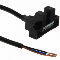
EE-SPX405-W2A
Manufacturer Part Number
EE-SPX405-W2A
Description
SENSOR OPTO 5MM LIGHT-ON TRANS
Manufacturer
Omron
Datasheets
1.EE-SPX304-W2A.pdf
(5 pages)
2.EE-1003A.pdf
(8 pages)
3.EE-SPX405-W2A.pdf
(4 pages)
4.EE-SPX405-W2A.pdf
(5 pages)
Specifications of EE-SPX405-W2A
Sensing Distance
0.197" (5mm)
Sensing Method
Transmissive
Output Configuration
NPN - Open Collector/Light-ON
Mounting Type
Chassis Mount
Current - Supply
15mA
Voltage - Supply
5 V ~ 24 V
Package / Case
Module, Pre-Wired
Termination Style
Cable
Input Current Max
50mA
Optocoupler Output Type
Transistor
Output Voltage
1V
Output Voltage Max
1V
Input Current
15mA
No. Of Pins
3
Opto Case Style
Slotted
Svhc
No SVHC (15-Dec-2010)
Frequency Response Max
500Hz
Sensing Range Max
5mm
Sensor Input
Optical
Supply Voltage Dc Max
24VDC
Connector Type
Prewired
External Depth
15.5mm
External Length /
RoHS Compliant
Operating Temperature Range
-10°C To +55°C
Operating Voltage Max
24VDC
Operating Voltage Min
5VDC
Rohs Compliant
Yes
Output Type
Light - On
Slot Width
5mm
External Length / Height
15.5mm
External Width
27.2mm
Lead Free Status / RoHS Status
Lead free / RoHS Compliant
Response Time
-
Lead Free Status / Rohs Status
Lead free / RoHS Compliant
Other names
EE-SPX405-W2A
EESPX405W2A
Z2357
EESPX405W2A
Z2357


EE-SPX305-W2A
EE-SPX405-W2A
EE-SPX-W
Reduced Installation Space
The total installation space, including the cable is less than that of the Connector-type Sensors.
Precautions
Refer to page NO TAG, Precautions in Technical Information, for
general precautions.
Wiring
Avoid disconnecting from the photomicrosensor when power is sup-
plied to the photomicrosensor or the photomicrosensor could be
damaged.
EE-SPX306-W2A
EE-SPX406-W2A
EE-SX671 + EE-1010
Installation space
ALL DIMENSIONS SHOWN ARE IN MILLIMETERS.
To convert millimeters into inches, multiply by 0.03937. To convert grams into ounces, multiply by 0.03527.
Two, 3.2 dia.
3.6
9
Optical axis
(0.5-mm wide)
* Three-conductor, thirteen, 0.12-wire cable (2-m long, 3.5 dia.)
20
27.2
Installation space
EE-SPX305-W2A
Optical axis
(1-mm wide)
15.5
20
14.4
12.7
(29.5 min.)
7.2
5
Light indicator
6.35
6.95
3.2
14.5
0.8
4-R2
N
Two, 3.5 dia. holes
1.5 max.
8±2
Optical axis (2 × 0.8)
Light indicator
Wire as shown by the following illustration to connect a small induc-
tive load (a relay for example) to the photomicrosensor. A diode
must be connected parallel to the relay to absorb the reverse volt-
age.
Installation space
EE-SX670 + EE-1010
7 dia.
1000
*
(3)
(1)
OUT
(2)
Terminal Arrangement
(1) Blue
(2) Black
(3) Brown
D
Relay
EE-SPX306-W2A
Installation space
EE-SPX-W
5 to 24 VDC
0 V
GND
OUT PUT
V
CC
(36.2 min.)
55
Related parts for EE-SPX405-W2A
Image
Part Number
Description
Manufacturer
Datasheet
Request
R

Part Number:
Description:
G6S-2GLow Signal Relay
Manufacturer:
Omron Corporation
Datasheet:
Part Number:
Description:
Compact, Low-cost, SSR Switching 5 to 20 A
Manufacturer:
Omron Corporation
Datasheet:
Part Number:
Description:
Manufacturer:
Omron Corporation
Datasheet:
Part Number:
Description:
Manufacturer:
Omron Corporation
Datasheet:
Part Number:
Description:
Manufacturer:
Omron Corporation
Datasheet:
Part Number:
Description:
Manufacturer:
Omron Corporation
Datasheet:
Part Number:
Description:
Manufacturer:
Omron Corporation
Datasheet:
Part Number:
Description:
Manufacturer:
Omron Corporation
Datasheet: