MCC19-12IO1B IXYS, MCC19-12IO1B Datasheet
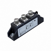
MOD THYRISTOR PHASE LEG TO-240AA

MCC19-12IO1B

Manufacturer Part Number
MCC19-12IO1B
Description
MOD THYRISTOR PHASE LEG TO-240AA
Manufacturer
IXYS
Datasheet

Specifications of MCC19-12IO1B

Structure
Series Connection - All SCRs
Number Of Scrs, Diodes
2 SCRs
Voltage - Off State
1200V
Current - Gate Trigger (igt) (max)
100mA
Current - On State (it (av)) (max)
25A
Current - On State (it (rms)) (max)
40A
Current - Non Rep. Surge 50, 60hz (itsm)
400A, 420A
Current - Hold (ih) (max)
200mA
Mounting Type
Chassis Mount
Package / Case
TO-240AA
Lead Free Status / RoHS Status
Lead free / RoHS Compliant
Other names
Q1268683
Q2732695

Available stocks

Company
Part Number
Manufacturer
Quantity
Price
Part Number:
MCC19-12IO1B
Manufacturer:
IXYS
Quantity:
492
Part Number:
MCC19-12IO1B
Quantity:
60
© 2000 IXYS All rights reserved
Thyristor Modules
Data according to IEC 60747 and refer to a single thyristor unless otherwise stated.
IXYS reserves the right to change limits, test conditions and dimensions
Symbol
I
I
I
òi
(di/dt)
(dv/dt)
P
P
V
T
T
T
V
M
Weight
1300
1500
1700
V
V
TRMS
TAVM
TSM
2
900
GM
GAV
RGM
VJ
VJM
stg
ISOL
V
d
RSM
DSM
dt
cr
cr
Test Conditions
T
T
T
T
V
T
V
T
V
T
V
T
f =50 Hz, t
V
I
di
T
R
T
I
50/60 Hz, RMS
I
Mounting torque (M5)
Terminal connection torque (M5)
Typical including screws
G
T
ISOL
VJ
C
C
VJ
VJ
VJ
VJ
VJ
VJ
VJ
R
R
R
R
D
GK
G
= I
= 0.45 A
/dt = 0.45 A/ms
1200
1400
1600
= 58°C; 180° sine
= 85°C; 180° sine
= 0
= 0
= 0
= 0
= 2/3 V
V
V
= T
= 45°C;
= T
= 45°C
= T
= T
= T
= T
= ¥; method 1 (linear voltage rise)
800
£ 1 mA
TAVM
V
RRM
DRM
VJM
VJM
VJM
VJM
VJM
VJM
;
DRM
P
=200 ms
MCC 19-12io1 B
MCC 19-14io1 B
MCC 19-16io1 B
Type
Version 1 B
MCC 19-08io1 B
t = 10 ms (50 Hz), sine
t = 8.3 ms (60 Hz), sine
t = 10 ms (50 Hz), sine
t = 8.3 ms (60 Hz), sine
t = 10 ms (50 Hz), sine
t = 8.3 ms (60 Hz), sine
t = 10 ms (50 Hz), sine
t = 8.3 ms (60 Hz), sine
repetitive, I
non repetitive, I
V
t
t
t = 1 min
t = 1 s
P
P
DR
= 30 ms
= 300 ms
= 2/3 V
T
DRM
= 45 A
T
= I
TAVM
Version 8 B
MCC 19-08io8 B
MCC 19-12io8 B
MCC 19-14io8 B
MCC 19-16io8 B
2.5-4.0/22-35 Nm/lb.in.
-40...+125
-40...+125
Maximum Ratings
1000
3600
3000
400
420
350
370
800
730
600
570
150
500
125
0.5
40
25
18
10
10
90
5
A/ms
A/ms
V/ms
A
A
A
A
V~
V~
°C
°C
°C
W
W
W
A
A
A
A
A
A
A
V
g
2
2
2
2
s
s
s
s
I
I
V
TO-240 AA
Version 1 B
Version 8 B
Features
Applications
Advantages
TRMS
TAVM
International standard package,
JEDEC TO-240 AA
Direct copper bonded Al
base plate
Planar passivated chips
Isolation voltage 3600 V~
UL registered, E 72873
Gate-cathode twin pins for version 1B
DC motor control
Softstart AC motor controller
Light, heat and temperature control
Space and weight savings
Simple mounting with two screws
Improved temperature and power
cycling
Reduced protection circuits
RRM
= 2x 40 A
= 2x 25 A
= 800-1600 V
1
2
3
3
3
MCC 19
6 7 1
6 1
2
O
3
6
-ceramic
7
4
5
5 4 2
1 - 4
5 2

Related parts for MCC19-12IO1B

MCC19-12IO1B Summary of contents

Page 1

... Terminal connection torque (M5) Weight Typical including screws Data according to IEC 60747 and refer to a single thyristor unless otherwise stated. IXYS reserves the right to change limits, test conditions and dimensions © 2000 IXYS All rights reserved Version 8 B MCC 19-08io8 B MCC 19-12io8 B ...

Page 2

... Keyed gate/cathode twin plugs with wire length = 350 mm, gate = yellow, cathode = red Type ZY 200L (L = Left for pin pair 4/5) Type ZY 200R (R = right for pin pair 6/7) Dimensions 0.0394") Version 1 B © 2000 IXYS All rights reserved Characteristic Values = V D DRM 2.05 = 125° ...

Page 3

... Fig. 3 Surge overload current I : Crest value, t: duration TSM © 2000 IXYS All rights reserved Fig. 4 ò versus time (1-10 ms) MCC 19 Fig. 4a Maximum forward current at case temperature Fig. 5 Power dissipation versus on- state current and ambient temperature (per thyristor) Fig. 6 Three phase rectifier bridge: ...

Page 4

... IXYS All rights reserved MCC 19 Fig. 7 Three phase AC-controller: Power dissipation versus RMS output current and ambient temperature Fig. 8 Transient thermal impedance junction to case (per thyristor) R for various conduction angles d: thJC d R (K/W) thJC DC 1.3 180° 1.35 120° ...

Related keywords