P103W Vishay, P103W Datasheet - Page 2
P103W
Manufacturer Part Number
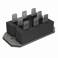
P103W
Description
SCR HY-BRIDGE 800V 25A PACE-PAK
Manufacturer
Vishay
Specifications of P103W
Structure
Bridge, Single Phase - SCRs/Diodes (Layout 1)
Number Of Scrs, Diodes
2 SCRs, 2 Diodes
Voltage - Off State
800V
Current - Gate Trigger (igt) (max)
60mA
Current - On State (it (rms)) (max)
25A (DC)
Current - Non Rep. Surge 50, 60hz (itsm)
357A, 375A
Current - Hold (ih) (max)
130mA
Mounting Type
Chassis Mount
Package / Case
6-PACE-PAK
Lead Free Status / RoHS Status
Lead free / RoHS Compliant
Current - On State (it (av)) (max)
-
Lead Free Status / RoHS Status
Lead free / RoHS Compliant, Lead free / RoHS Compliant
Other names
*P103W
VS-P103W
VS-P103W
VSP103W
VSP103W
VS-P103W
VS-P103W
VSP103W
VSP103W
Available stocks
Company
Part Number
Manufacturer
Quantity
Price


P100 Series
Bulletin I27125 rev. A 04/99
2
ELECTRICAL SPECIFICATIONS
Voltage Ratings
On-state Conduction
I
I
I
I
I
V
r
V
V
di/dt
I
I
2
2
H
L
D
TSM
FSM
t1
Type number
P101, P121, P131
P102, P122, P132
P103, P123, P133
P104, P124, P134
P105, P125, P135
t
T(TO)
TM
FM
t
Parameter
Maximum DC output current
Max. peak one-cycle
non-repetitive on-state
or forward current
Maximum I
Maximum I
Max. value of threshold voltage
Max. level value of on-state
slope resistance
Max. peak on-state or
forward voltage drop
Maximum non repetitive rate of
rise of turned on current
Maximum holding current
Maximum latching current
2
2
t for fusing
t for fusing
V
RRM
peak reverse voltage
maximum repetitive
1000
1200
400
600
800
V
6365
P100
0.82
1.35
357
375
300
315
637
580
450
410
130
250
2 5
200
12
repetitive peak reverse repetitive peak off-state
V
RSM
Units Conditions
maximum non-
A
m
A/µs
A
mA
mA
voltage
2
A
V
V
A
2
1100
1300
500
700
900
s
s
V
@ T
t = 10ms
t = 8.3ms
t = 10ms
t = 8.3ms
t = 10ms
t = 8.3ms
t = 10ms
t = 8.3ms
t = 0.1 to 10ms, no voltage reapplied
I
T
T
T
T
I
T
T
TM
2
J
J
J
J
J
J
t for time tx = I
= 125°C, Av. power = V
= 25°C, I
= 25°C anode supply = 6V, resistive load, gate open
= 25°C anode supply = 6V, resistive load
= 125°C
= 125°C from 0.67 V
= x I
C
= 85°C, full bridge
T(AV)
TM
No voltage
reapplied
100% V
reapplied
No voltage
reapplied
100% V
reapplied
, I
= x I
g
V
= 500mA, tr < 0.5µs, tp > 6µs
DRM
2
t
T(AV)
voltage
RRM
RRM
.
maximum
1000
1200
400
600
800
DRM
V
tx
T(TO)
Sinusoidal half wave,
Initial T
* I
T(AV)
J
= T
+ r
www.irf.com
t
J
+ (I
@ T
I
max.
RRM
T(RMS)
mA
10
J
max.
max.
)
2
Related parts for P103W
Image
Part Number
Description
Manufacturer
Datasheet
Request
R

Part Number:
Description:
SCR Modules 800 Volt 25 Amp
Manufacturer:
Vishay
Datasheet:

Part Number:
Description:
357-036-542-201 CARDEDGE 36POS DL .156 BLK LOPRO
Manufacturer:
Vishay
Datasheet:
Part Number:
Description:
357-036-542-201 CARDEDGE 36POS DL .156 BLK LOPRO
Manufacturer:
Vishay
Datasheet:
Part Number:
Description:
357-036-542-201 CARDEDGE 36POS DL .156 BLK LOPRO
Manufacturer:
Vishay
Datasheet:
Part Number:
Description:
357-036-542-201 CARDEDGE 36POS DL .156 BLK LOPRO
Manufacturer:
Vishay
Datasheet:
Part Number:
Description:
357-036-542-201 CARDEDGE 36POS DL .156 BLK LOPRO
Manufacturer:
Vishay
Datasheet:
Part Number:
Description:
357-036-542-201 CARDEDGE 36POS DL .156 BLK LOPRO
Manufacturer:
Vishay
Datasheet:
Part Number:
Description:
357-036-542-201 CARDEDGE 36POS DL .156 BLK LOPRO
Manufacturer:
Vishay
Datasheet:
Part Number:
Description:
357-036-542-201 CARDEDGE 36POS DL .156 BLK LOPRO
Manufacturer:
Vishay
Datasheet:
Part Number:
Description:
357-036-542-201 CARDEDGE 36POS DL .156 BLK LOPRO
Manufacturer:
Vishay
Datasheet:
Part Number:
Description:
357-036-542-201 CARDEDGE 36POS DL .156 BLK LOPRO
Manufacturer:
Vishay
Datasheet:
Part Number:
Description:
357-036-542-201 CARDEDGE 36POS DL .156 BLK LOPRO
Manufacturer:
Vishay
Datasheet:
Part Number:
Description:
357-036-542-201 CARDEDGE 36POS DL .156 BLK LOPRO
Manufacturer:
Vishay
Datasheet:
Part Number:
Description:
357-036-542-201 CARDEDGE 36POS DL .156 BLK LOPRO
Manufacturer:
Vishay
Datasheet:
Part Number:
Description:
357-036-542-201 CARDEDGE 36POS DL .156 BLK LOPRO
Manufacturer:
Vishay
Datasheet: