PM200DVA120 Powerex Inc, PM200DVA120 Datasheet - Page 4
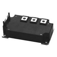
PM200DVA120
Manufacturer Part Number
PM200DVA120
Description
MOD IPM V-SER DUAL 1200V 200A
Manufacturer
Powerex Inc
Series
Intellimod™r
Type
IGBTr
Datasheet
1.PM200DVA120.pdf
(6 pages)
Specifications of PM200DVA120
Configuration
1 Phase Inverter
Current
200A
Voltage
1200V
Voltage - Isolation
2500Vrms
Package / Case
Module
Transistor Polarity
N Channel
Dc Collector Current
200A
Collector Emitter Voltage Vces
1.2kV
Power Dissipation Pd
962W
Collector Emitter Voltage V(br)ceo
1.2kV
Prx Availability
RequestQuote
Distributorinventory
View
Circuit Configuration
Dual
Package
120x70x29mm
Rohs Compliant
Yes
Lead Free Status / RoHS Status
Lead free / RoHS Compliant
Available stocks
Company
Part Number
Manufacturer
Quantity
Price
Company:

Part Number:
PM200DVA120
Manufacturer:
AMD
Quantity:
649
Company:
Part Number:
PM200DVA120
Manufacturer:
MITSUBISHI
Quantity:
38
Part Number:
PM200DVA120
Manufacturer:
MIT
Quantity:
20 000
Part Number:
PM200DVA120
Quantity:
60
Company:
Part Number:
PM200DVA120-02
Manufacturer:
MITSUBISHI
Quantity:
560


446
Powerex, Inc., 200 Hillis Street, Youngwood, Pennsylvania 15697-1800 (724) 925-7272
PM200DVA120
Intellimod™ Module
Single Phase IGBT Inverter Output
200 Amperes/1200 Volts
Electrical and Mechanical Characteristics, T
Characteristics
IGBT Inverter Sector
Collector-Emitter Cutoff Current
FWDi Forward Voltage
Collector-Emitter Saturation Voltage
Inductive Load Switching Times
Thermal Characteristics
Characteristic
Junction to Case Thermal Resistance
Contact Thermal Resistance
Recommended Conditions for Use
Characteristic
Supply Voltage
Input ON Voltage
Input OFF Voltage
Arm Shoot-Through Blocking Time
V
V
V
V
R
R
CE(surge)
Symbol
Symbol
R
Symbol
t
t
t
CE(sat)
CIN(on)
CIN(off)
th(j-c)Q
th(j-c)D
DEAD
I
V
C(on)
C(off)
V
th(c-f)
CES
V
t
t
t
on
off
EC
CC
rr
D
j
V
= 25 C unless otherwise specified
CE
Applied across C1-E1, C2-E2 Terminals
= V
V
-I
V
V
Applied across C1-E2 Terminals
CE
C
CES
D
D
For IPM's each Input Signal
V
= 200A, V
= 15V, V
= 15V, V
Thermal Grease Applied
Case to Fin Per Module,
V
= V
D
, V
CC
Each Inverter FWDi
C
Each Inverter IGBT
V
= 15V, V
Pulsed, T
Pulsed, T
CES
Applied between
P1
Applied between
P1
Test Conditions
D
= 600V, I
-V
-V
= 15V, T
T
Condition
Condition
, V
CIN
CIN
j
PC
PC
D
= 125 C
D
CIN
= 15V, V
, C
, V
= 0V, I
= 0V, I
j
= 15V, T
j
= 125 C
= 25 C
C
N1
N1
j
= 0V ~ 5V
= 125 C
= 200A,
-V
-V
C
C
NC
NC
CIN
= 200A,
= 200A,
j
= 25 C
= 5V
—
Min.
Min.
0.4
—
—
—
—
—
—
—
—
—
—
—
—
2.50
2.65
2.75
Typ.
0.9
0.2
0.4
2.4
0.7
Typ.
—
—
—
—
10.0
15
0.081
Value
Max.
Max.
3.50
3.30
3.35
0.11
0.18
1.0
2.3
0.3
1.0
3.4
1.2
1000
800
0.8
4.0
3.5
1.5
C/Watt
C/Watt
C/Watt
Units
Volts
Volts
Volts
Units
Units
Volts
Volts
Volts
Volts
Volts
mA
mA
S
S
S
S
S
S
Related parts for PM200DVA120
Image
Part Number
Description
Manufacturer
Datasheet
Request
R

Part Number:
Description:
Manufacturer:
TDK Corporation
Datasheet:
Part Number:
Description:
Manufacturer:
TDK Corporation
Datasheet:
Part Number:
Description:
Manufacturer:
TDK Corporation
Datasheet:
Part Number:
Description:
Manufacturer:
TDK Corporation
Datasheet:

Part Number:
Description:
INDUCTOR CHIP.018UH 20% 1210 SMD
Manufacturer:
JW Miller A Bourns Company
Datasheet:
Part Number:
Description:
INDUCTOR CHIP 10UH 10% 1210 SMD
Manufacturer:
JW Miller A Bourns Company
Datasheet:
Part Number:
Description:
INDUCTOR CHIP 100UH 10% 1210 SMD
Manufacturer:
JW Miller A Bourns Company
Datasheet:
Part Number:
Description:
INDUCTOR CHIP 12UH 10% 1210 SMD
Manufacturer:
JW Miller A Bourns Company
Datasheet:
Part Number:
Description:
INDUCTOR CHIP 120UH 10% 1210 SMD
Manufacturer:
JW Miller A Bourns Company
Datasheet:
Part Number:
Description:
INDUCTOR CHIP 15UH 10% 1210 SMD
Manufacturer:
JW Miller A Bourns Company
Datasheet:

Part Number:
Description:
Manufacturer:
Powerex Inc
Datasheet:
Part Number:
Description:
Manufacturer:
Powerex Inc
Datasheet:
Part Number:
Description:
Manufacturer:
Powerex Inc
Datasheet:
Part Number:
Description:
Manufacturer:
Powerex Inc
Datasheet:
Part Number:
Description:
Manufacturer:
Powerex Inc
Datasheet: