PM75RLB060 Powerex Inc, PM75RLB060 Datasheet - Page 2
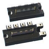
PM75RLB060
Manufacturer Part Number
PM75RLB060
Description
MOD IPM L-SERIES 600V 75A
Manufacturer
Powerex Inc
Series
Intellimod™r
Type
IGBTr
Datasheet
1.PM75RLB060.pdf
(6 pages)
Specifications of PM75RLB060
Configuration
3 Phase Inverter
Current
75A
Voltage
600V
Voltage - Isolation
2500VDC
Package / Case
Module
Power Dissipation Pd
300W
Collector Emitter Voltage V(br)ceo
600V
Continuous Collector Current Ic
75A
Collector Emitter Saturation Voltage Vce(sat)
2.1V
Output Current
75A
Leaded Process Compatible
Yes
Operating Voltage
600V
Rohs Compliant
Yes
Circuit Configuration
7-Pac
Package
120x55mm - B
Recommended Accessory
BP7B-LS
Lead Free Status / RoHS Status
Lead free / RoHS Compliant
For Use With
BP7B-LS - KIT DEV INTERFACE FOR IPMBP7A-LS - KIT DEV INTERFACE FOR IPM
Lead Free Status / RoHS Status
Lead free / RoHS Compliant, Lead free / RoHS Compliant
Available stocks
Company
Part Number
Manufacturer
Quantity
Price
Company:

Part Number:
PM75RLB060
Manufacturer:
APT
Quantity:
430


2
Powerex, Inc., 200 E. Hillis Street, Youngwood, Pennsylvania 15697-1800 (724) 925-7272
PM75RLB060
Intellimod™ L-Series
Three Phase IGBT Inverter + Brake
75 Amperes/600 Volts
Absolute Maximum Ratings, T
Characteristics
Power Device Junction Temperature
Storage Temperature
Mounting Torque, M5 Mounting Screws
Module Weight (Typical)
Supply Voltage, Surge (Applied between P - N)
Self-protection Supply Voltage Limit (Short Circuit protection Capability)*
Isolation Voltage, AC 1 minute, 60Hz Sinusoidal
*VD = 13.5 ~ 16.5V, Inverter Part, Tj = 125°C
IGBT Inverter Sector
Collector-Emitter Voltage (V
Collector Current (T
Peak Collector Current (T
Collector Dissipation (T
IGBT Brake Sector
Collector-Emitter Voltage (V
Collector Current (T
Peak Collector Current (T
Collector Dissipation (T
Diode Rated DC Reverse Voltage (T
Diode Forward Current
Control Sector
Supply Voltage (Applied between V
Input Voltage (Applied between U
Fault Output Supply Voltage
(Applied between U
Fault Output Current (U
Note 1:T
Measurement Point
MEASUREMENT
C
TOP VIEW
POINT
(Base Plate)
T C
FO
C
C
= 25°C)
= 25°C)
-V
C
C
FO
UPC
C
= 25°C)
C
= 25°C)
, V
D
= 25°C)
D
= 25°C)
FO
, V
= 15V, V
= 15V, V
FO
, W
P
-V
-V
FO
UP1
C
VPC
UPC
, F
CIN
CIN
= 25°C)
-V
j
O
, W
Axis
UPC
, V
= 25°C unless otherwise specified
= 15V)
= 15V)
Terminals)
P
FO
Arm
Y
X
-V
, V
-V
VPC
VP1
WPC
, W
-V
IGBT FWDi IGBT FWDi IGBT FWDi IGBT FWDi IGBT FWDi IGBT FWDi IGBT FWDi
28.7
-6.6
, F
VPC
P
-V
UP
O
-V
, V
WPC
28.7
0.85
NC
WP1
, U
)
-V
65.2
-6.6
N
- V
WPC
VP
N
- W
65.2
, V
2.5
N1
N
-Br-V
Note 2: T
-V
85.3
Y
-6.6
NC
Measurement Point
X
NC
WP
)
85.3
)
2.5
C
BOTTOM VIEW
V
V
(Under the Chip)
CC(surge)
V
Symbol
CC(prot.)
V
V
V
V
±I
±I
R(DC)
V
T
38.0
±I
±I
I
P
P
V
CES
CES
—
—
FO
4.6
T
ISO
I
CIN
stg
FO
CP
CP
F
C
C
D
C
C
j
UN
38.0
-4.5
55.4
4.6
VN
PM75RLB060
-20 to 150
-40 to 125
55.4
-4.5
2500
340
550
400
600
150
300
600
100
228
600
31
75
50
50
20
20
20
20
75.5
4.6
WN
75.5
-4.5
19.0
-7.3
Amperes
Amperes
Amperes
Amperes
Amperes
Grams
Watts
Watts
Units
Volts
Volts
Volts
Volts
Volts
Volts
Volts
Volts
Volts
in-lb
mA
°C
°C
Br
23.0
6.6
Related parts for PM75RLB060
Image
Part Number
Description
Manufacturer
Datasheet
Request
R

Part Number:
Description:
INDUCTOR UNSHIELD 12UH 10% SMT
Manufacturer:
JW Miller A Bourns Company
Datasheet:
Part Number:
Description:
INDUCTOR UNSHIELD 120UH 10% SMT
Manufacturer:
JW Miller A Bourns Company
Datasheet:
Part Number:
Description:
INDUCTOR UNSHIELD 15UH 10% SMT
Manufacturer:
JW Miller A Bourns Company
Datasheet:
Part Number:
Description:
INDUCTOR UNSHIELD 150UH 10% SMT
Manufacturer:
JW Miller A Bourns Company
Datasheet:
Part Number:
Description:
INDUCTOR UNSHIELD 18UH 10% SMT
Manufacturer:
JW Miller A Bourns Company
Datasheet:
Part Number:
Description:
INDUCTOR UNSHIELD 180UH 10% SMT
Manufacturer:
JW Miller A Bourns Company
Datasheet:
Part Number:
Description:
INDUCTOR UNSHIELD 22UH 10% SMT
Manufacturer:
JW Miller A Bourns Company
Datasheet:
Part Number:
Description:
INDUCTOR UNSHIELD 220UH 10% SMT
Manufacturer:
JW Miller A Bourns Company
Datasheet:
Part Number:
Description:
INDUCTOR UNSHIELD 27UH 10% SMT
Manufacturer:
JW Miller A Bourns Company
Datasheet:
Part Number:
Description:
INDUCTOR UNSHIELD 270UH 10% SMT
Manufacturer:
JW Miller A Bourns Company
Datasheet:

Part Number:
Description:
Manufacturer:
Powerex Inc
Datasheet:
Part Number:
Description:
Manufacturer:
Powerex Inc
Datasheet:
Part Number:
Description:
Manufacturer:
Powerex Inc
Datasheet:
Part Number:
Description:
Manufacturer:
Powerex Inc
Datasheet:
Part Number:
Description:
Manufacturer:
Powerex Inc
Datasheet: