PM25RLB120 Powerex Inc, PM25RLB120 Datasheet - Page 3
PM25RLB120
Manufacturer Part Number
PM25RLB120
Description
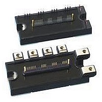
MOD IPM L-SER 7PAC 1200V 25A
Manufacturer
Powerex Inc
Series
Intellimod™r
Type
IGBTr
Datasheet
1.PM25RLB120.pdf
(6 pages)
Specifications of PM25RLB120
Configuration
3 Phase Inverter
Current
25A
Voltage
1200V
Voltage - Isolation
2500VDC
Package / Case
Module
Power Dissipation Pd
116W
Collector Emitter Voltage V(br)ceo
1.2kV
Continuous Collector Current Ic
25A
Collector Emitter Saturation Voltage Vce(sat)
2.3V
Output Current
25A
Leaded Process Compatible
Yes
Operating Voltage
1.2kV
Rohs Compliant
Yes
Circuit Configuration
7-Pac
Package
120x55mm - B
Recommended Accessory
BP7B-LS
Lead Free Status / RoHS Status
Lead free / RoHS Compliant
For Use With
BP7B-LS - KIT DEV INTERFACE FOR IPMBP7A-LS - KIT DEV INTERFACE FOR IPM
Lead Free Status / RoHS Status
Lead free / RoHS Compliant, Lead free / RoHS Compliant
Available stocks
Company
Part Number
Manufacturer
Quantity
Price
Company:

Part Number:
PM25RLB120
Manufacturer:
MITS
Quantity:
1 000
Part Number:
PM25RLB120
Manufacturer:
MITSUBISHI/三菱
Quantity:
20 000
Part Number:
PM25RLB120
Quantity:
60


Powerex, Inc., 200 E. Hillis Street, Youngwood, Pennsylvania 15697-1800 (724) 925-7272
PM25RLB120
Intellimod™ L-Series
Three Phase IGBT Inverter + Brake
25 Amperes/1200 Volts
Electrical and Mechanical Characteristics, T
Characteristics
IGBT Inverter Sector
Collector-Emitter Cutoff Current
Diode Forward Voltage
Collector-Emitter Saturation Voltage
Inductive Load Switching Times
IGBT Brake Sector
Collector-Emitter Cutoff Current
Diode Forward Voltage
Collector-Emitter Saturation Voltage
Control Sector
Short Circuit Trip Level
(-20°C ≤ T
Short Circuit Current Delay Time
Over Temperature Protection
(Detect T
Supply Circuit Under-voltage Protection
(-20 ≤ T
Circuit Current
Input ON Threshold Voltage
Input OFF Threshold Voltage
Fault Output Current*
Fault Output Pulse Width*
*Fault output is given only when the internal SC, OT and UV protections schemes of either upper or lower devide operate to protect it.
j
≤ 125°C)
j
j
of IGBT Chip)
≤ 125°C, V
D
= 15V)
V
V
Symbol
t
V
V
I
off(SC)
I
t
t
CE(sat)
CE(sat)
I
I
FO(H)
C(on)
C(off)
V
OT
UV
FO(L)
V
th(on)
th(off)
CES
CES
t
SC
OT
UV
t
t
t
I
FO
on
off
EC
FM
rr
D
R
R
j
= 25°C unless otherwise specified
V
P
-V
V
V
V
V
V
-I
CE
CE
V
VPC
D
V
V
V
V
CE
CE
C
D
D
D
D
D
= 15V, V
Applied between U
V
= 25A, V
= V
= V
= 15V, V
= 15V, V
= 15V, V
D
= 15V, V
= 15V, V
, W
= V
= V
V
V
V
= 15V, V
CC
D
D
CES
CES
P
CES
CES
Test Conditions
-V
= 15V, V
= 15V, V
Inverter Part
= 600V, I
Reset Level
Reset Level
T
T
T
Brake Part
CIN
, V
, V
WPC
V
Trip Level
Trip Level
V
T
T
, V
CIN
, V
I
CIN
j
j
j
CIN
CIN
F
CIN
CIN
j
j
D
D
= 125°C
= 125°C
= 125°C
D
D
= 25°C
= 25°C
D
D
= 15A
CIN
= 15V, V
= 15V
= 15V
= 15V, T
= 15V, T
, U
= 15V, V
= 15V, V
= 15V, T
= 15V, T
= 0V, I
= 0V, I
= 0V, I
= 0V, I
CIN
CIN
N
= 0 ⇔ 15V
C
- V
= 25A
= 15V
= 15V
P
-V
N
C
C
C
C
XP1
- W
j
D
j
N1
j
j
UPC
= 25A,
= 25A,
= 15A,
= 15A,
= 125°C
= 125°C
= 25°C
= 25°C
= 15V
-V
-V
N
,
-Br-V
NC
XPC
NC
Min.
11.5
135
0.5
1.2
1.7
1.0
50
30
—
—
—
—
—
—
—
—
—
—
—
—
—
—
—
—
—
—
—
—
—
12.0
12.5
145
125
Typ.
2.5
1.8
1.9
1.0
0.5
0.4
2.0
0.7
2.5
1.8
1.9
0.2
1.5
2.0
1.8
20
10
—
—
—
—
—
—
—
5
Max.
12.5
0.01
155
1.0
3.5
2.3
2.4
2.5
0.8
1.0
3.0
1.2
1.0
3.5
2.3
2.4
1.8
2.3
10
10
—
—
—
—
—
30
10
15
—
Amperes
Amperes
Units
Volts
Volts
Volts
Volts
Volts
Volts
Volts
Volts
Volts
Volts
mA
mA
mA
mA
mA
mA
mA
mA
ms
µs
µs
µs
µs
µs
µs
°C
°C
3
Related parts for PM25RLB120
Image
Part Number
Description
Manufacturer
Datasheet
Request
R

Part Number:
Description:
Power Module Power Modules Standard Power - Switchbox Ac/dc . Switchbox Pm25 Series Dc-dc Converter
Manufacturer:
Powerbox
Datasheet:
Part Number:
Description:
25-28 WATTS SINGLE & MULTIPLE OUTPUT AC/DC MEDICAL
Manufacturer:
POWERBOX [Powerbox]
Datasheet:

Part Number:
Description:
Manufacturer:
Powerex Inc
Datasheet:
Part Number:
Description:
Manufacturer:
Powerex Inc
Datasheet:
Part Number:
Description:
Manufacturer:
Powerex Inc
Datasheet:
Part Number:
Description:
Manufacturer:
Powerex Inc
Datasheet:
Part Number:
Description:
Manufacturer:
Powerex Inc
Datasheet:
Part Number:
Description:
Manufacturer:
Powerex Inc
Datasheet:
Part Number:
Description:
Manufacturer:
Powerex Inc
Datasheet:
Part Number:
Description:
Manufacturer:
Powerex Inc
Datasheet:
Part Number:
Description:
Manufacturer:
Powerex Inc
Datasheet:
Part Number:
Description:
Manufacturer:
Powerex Inc
Datasheet:
Part Number:
Description:
Manufacturer:
Powerex Inc
Datasheet:
Part Number:
Description:
Manufacturer:
Powerex Inc
Datasheet: