PS21A79 Powerex Inc, PS21A79 Datasheet - Page 7
PS21A79
Manufacturer Part Number
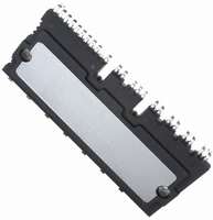
PS21A79
Description
MOD IPM 600V 50A LARGE DIP
Manufacturer
Powerex Inc
Series
DIPIPM™r
Type
IGBTr
Datasheet
1.PS21A79.pdf
(7 pages)
Specifications of PS21A79
Configuration
3 Phase
Current
50A
Voltage
600V
Voltage - Isolation
2500VDC
Package / Case
PCB Module
Dc Collector Current
50A
Collector Emitter Voltage Vces
600V
Power Dissipation Pd
142W
Collector Emitter Voltage V(br)ceo
600V
Operating Temperature Range
-20°C To +100°C
No. Of Pins
42
Lead Free Status / RoHS Status
Lead free / RoHS Compliant
Other names
835-1045
Available stocks
Company
Part Number
Manufacturer
Quantity
Price
Company:

Part Number:
PS21A79
Manufacturer:
QUALCOMM
Quantity:
2 000
Part Number:
PS21A79
Manufacturer:
MITSUBISHI/三菱
Quantity:
20 000


Powerex, Inc., 173 Pavilion Lane, Youngwood, Pennsylvania 15697 (724) 925-7272
PS21A79
Intellimod™ Module
Dual-In-Line Intelligent Power Module
50 Amperes/600 Volts
Protection Function Timing Diagrams
Typical Interface Circuit
Wiring Method Around Shunt Resistor
Rev. 08/09
MCU
Under-Voltage Protection (P-side, UV DB )
OUTPUT CURRENT I C
V NC
CONTROL SUPPLY
FAULT OUTPUT F O
DIPIPM
CONTROL INPUT
CIRCUIT STATE
c1: Control supply voltage V DB rises – After V DB level reaches under voltage reset level (UV DBr ),
c2: Normal operation – IGBT turns on and carries current.
c3: V DB level dips to under voltage trip level (UV DBt ).
c4: P-side IGBT turns off in spite of control input signal level, but there is no F O signal output.
c5: V DB level reaches UV DBr .
c6: Normal operation – IGBT on and carries current.
VOLTAGE V DB
PROTECTION
NW
the circuits starts to operate when next input is applied.
NU
NV
10kΩ
Detecting Circuit
5V LINE
UV DBr
To Current
HIGH LEVEL (NO FAULT OUTPUT)
RESET
Resistors
Shunt
It is recommended to make the inductance under 10nH.
For shunt resistors, it is recommended to use as low
inductance type as possible.
c1
U P , V P , W P , U N , V N , W N
V NC (LOGIC)
F O
DIP-IPM
UV Dt
Connect the wiring from V NC terminal at the point as
close to shunt resistors’ terminal as possible.
It is recommended to divide the wiring to current detecting
circuit at the point as close to shunt resistor’s terminal as
possible.
c2
SET
c3
2.5kΩ (MIN)
c4
RESET
c5
NOTE: RC coupling at each input
(parts shown dotted) may change
depending on the PWM control
scheme used in the application and
the wiring impedance of the printed
circuit board. The DIPIPM input signal
section integrates a 2.5k Ω (min)
pull-down resistor. Therefore, when
using an external filtering resistor, care
must be taken to satisfy the turn-on
threshold voltage requirement.
c6
7
Related parts for PS21A79
Image
Part Number
Description
Manufacturer
Datasheet
Request
R

Part Number:
Description:
Manufacturer:
Powerex Inc
Datasheet:
Part Number:
Description:
Manufacturer:
Powerex Inc
Datasheet:
Part Number:
Description:
Manufacturer:
Powerex Inc
Datasheet:
Part Number:
Description:
Manufacturer:
Powerex Inc
Datasheet:
Part Number:
Description:
Manufacturer:
Powerex Inc
Datasheet:
Part Number:
Description:
Manufacturer:
Powerex Inc
Datasheet:
Part Number:
Description:
Manufacturer:
Powerex Inc
Datasheet:
Part Number:
Description:
Manufacturer:
Powerex Inc
Datasheet:
Part Number:
Description:
Manufacturer:
Powerex Inc
Datasheet:
Part Number:
Description:
Manufacturer:
Powerex Inc
Datasheet:
Part Number:
Description:
Manufacturer:
Powerex Inc
Datasheet:
Part Number:
Description:
Manufacturer:
Powerex Inc
Datasheet:
Part Number:
Description:
Manufacturer:
Powerex Inc
Datasheet:
Part Number:
Description:
Manufacturer:
Powerex Inc
Datasheet: