IRAMY20UP60B International Rectifier, IRAMY20UP60B Datasheet - Page 9
IRAMY20UP60B
Manufacturer Part Number
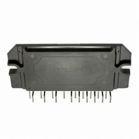
IRAMY20UP60B
Description
IC PWR HYBRID 600V 20A SIP3
Manufacturer
International Rectifier
Series
iMOTION™r
Type
IGBTr
Datasheet
1.IRAMY20UP60B.pdf
(16 pages)
Specifications of IRAMY20UP60B
Configuration
3 Phase
Current
20A
Voltage
600V
Voltage - Isolation
2000Vrms
Package / Case
SIP3
Current, Input Bias
200 μA
Current, Quiescent Supply
165 μA
Current, Rms Phase
20 A
Frequency
20 KHz
Number Of Pins
25
Power Dissipation
4.5 W
Switching Loss
495 μJ
Temperature, Junction, Maximum
150 °C
Voltage, Breakdown, Collector To Emitter
600 V
Voltage, Input
20 + 0.3 V
Voltage, Input, High Level
20 + 0.3 V
Voltage, Input, Low Level
20 + 0.3 V
Voltage, Supply
20 V
No. Of Outputs
3
Output Current
20A
Output Voltage
450V
Supply Voltage Range
12V To 20V
Driver Case Style
SIP
No. Of Pins
23
Operating Temperature Range
-40°C To +150°C
Rohs Compliant
Yes
Operating Temperature Classification
Automotive
Motor Controller Type
Motor Driver
Operating Supply Voltage (min)
12V
Operating Supply Voltage (max)
20V
Lead Free Status / RoHS Status
Lead free / RoHS Compliant
Available stocks
Company
Part Number
Manufacturer
Quantity
Price
Company:

Part Number:
IRAMY20UP60B
Manufacturer:
SPREADTRU
Quantity:
3 000


Typical Application Connection IRAMY20UP60B
1. Electrolytic bus capacitors should be mounted as close to the module bus terminals as possible to reduce ringing and
EMI problems. Additional high frequency ceramic capacitor mounted close to the module pins will further improve per-
formance.
2. In order to provide good decoupling between V
between these terminals should be located very close to the module pins. Additional high frequency capacitors, typi-
cally 0.1µF, are strongly recommended.
3. Value of the boot-strap capacitors depends upon the switching frequency. Their selection should be made based on
IR design tip DN 98-2a, application note AN-1044 or Figure 9. Bootstrap capacitor value must be selected to limit the
power dissipation of the internal resistor in series with the V
4. Current sense signal can be obtained from pin 20 and pin 22. Care should be taken to avoid having inverter current
flowing through pin 22 to mantain required current measurement accuracy
5. After approx. 8ms the FAULT is reset. (see Dynamic Characteristics Table on page 5).
6. PWM generator must be disabled within Fault duration to guarantee shutdown of the system, overcurrent condition
must be cleared before resuming operation.
7. Fault/Temp Monitor pin must be pulled-up to +5V.
www.irf.com
CONTROLLER
V
+
PGND
CAPACITORS
Fault & Temp
DC BUS
Monitor
+5V
I
Monitor
+15V
3-Phase AC
12kohm
MOTOR
0.1mF
+5V
W
U
V
CC
BOOT-STRAP
CAPACITORS
-V
DGND
10mF
SS
and V
CC
. (see maximum ratings Table on page 3).
B1,2,3
C
BS
-V
V
FLT-V
cc
S1,2,3
HIN1
HIN2
HIN3
LIN1
LIN2
LIN3
I
TRIP
(15 V)
V
V
+
-
V
SS
TH
terminals, the capacitors shown connected
V
V
V
B1
B2
B3
V
V
V
S1
S2
S3
IRAMY20UP60B
9
Related parts for IRAMY20UP60B
Image
Part Number
Description
Manufacturer
Datasheet
Request
R

Part Number:
Description:
SCHOTTKY RECTIFIER
Manufacturer:
International Rectifier Corp.
Datasheet:
Part Number:
Description:
SCHOTTKY RECTIFIER
Manufacturer:
International Rectifier Corp.
Datasheet:
Part Number:
Description:
SCHOTTKY RECTIFIER
Manufacturer:
International Rectifier Corp.
Datasheet:
Part Number:
Description:
SCHOTTKY RECTIFIER
Manufacturer:
International Rectifier Corp.
Datasheet:
Part Number:
Description:
SCHOTTKY RECTIFIER
Manufacturer:
International Rectifier Corp.
Datasheet:
Part Number:
Description:
SCHOTTKY RECTIFIER
Manufacturer:
International Rectifier Corp.
Datasheet:
Part Number:
Description:
SCHOTTKY RECTIFIER
Manufacturer:
International Rectifier Corp.
Datasheet:
Part Number:
Description:
SCHOTTKY RECTIFIER
Manufacturer:
International Rectifier Corp.
Datasheet:
Part Number:
Description:
SCHOTTKY RECTIFIER
Manufacturer:
International Rectifier Corp.
Datasheet:
Part Number:
Description:
SCHOTTKY RECTIFIER
Manufacturer:
International Rectifier Corp.
Datasheet:
Part Number:
Description:
SCHOTTKY RECTIFIER
Manufacturer:
International Rectifier Corp.
Datasheet:
Part Number:
Description:
SCHOTTKY RECTIFIER
Manufacturer:
International Rectifier Corp.
Datasheet:
Part Number:
Description:
SCHOTTKY RECTIFIER
Manufacturer:
International Rectifier Corp.
Datasheet:
Part Number:
Description:
SCHOTTKY RECTIFIER
Manufacturer:
International Rectifier Corp.
Datasheet:
Part Number:
Description:
SCHOTTKY RECTIFIER
Manufacturer:
International Rectifier Corp.
Datasheet: