GA200SA60S Vishay, GA200SA60S Datasheet - Page 5
GA200SA60S
Manufacturer Part Number
GA200SA60S
Description
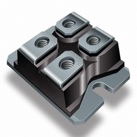
IGBT STD 600V 100A SOT227
Manufacturer
Vishay
Datasheet
1.GA200SA60S.pdf
(8 pages)
Specifications of GA200SA60S
Configuration
Single
Voltage - Collector Emitter Breakdown (max)
600V
Vce(on) (max) @ Vge, Ic
1.3V @ 15V, 100A
Current - Collector (ic) (max)
200A
Current - Collector Cutoff (max)
1mA
Input Capacitance (cies) @ Vce
16.25nF @ 30V
Power - Max
630W
Input
Standard
Ntc Thermistor
No
Mounting Type
Chassis Mount
Package / Case
SOT-227, miniBLOC
Lead Free Status / RoHS Status
Contains lead / RoHS non-compliant
Igbt Type
-
Other names
*GA200SA60S
VS-GA200SA60S
VS-GA200SA60S
VSGA200SA60S
VSGA200SA60S
VS-GA200SA60S
VS-GA200SA60S
VSGA200SA60S
VSGA200SA60S
Available stocks
Company
Part Number
Manufacturer
Quantity
Price
Company:

Part Number:
GA200SA60S
Manufacturer:
IR
Quantity:
1 000
Part Number:
GA200SA60S
Quantity:
60
Company:
Part Number:
GA200SA60SP
Manufacturer:
IR
Quantity:
1 000
Part Number:
GA200SA60SP
Quantity:
61


www.irf.com
Fig. 9 - Typical Switching Losses vs. Gate
30000
24000
18000
12000
25
24
23
22
21
20
19
18
6000
0
0
V
V
T
Fig. 7 - Typical Capacitance vs.
I
J
C
1
CC
GE
= 480V
= 15V
= 25
= 200A
R
C ies
C oes
C res
10
V
Collector-to-Emitter Voltage
G
CE
°
, Gate Resistance (Ohm)
C
V
C
C
C
, Collector-to-Emitter Voltage (V)
Resistance
GE
ies
res
oes
=
=
=
=
20
0V,
C
C
C
ge
gc
ce
+ C
+ C
10
f = 1MHz
gc ,
gc
30
C
ce
( Ω )
40
SHORTED
50
100
1000
100
20
16
12
10
8
4
0
Fig. 10 - Typical Switching Losses vs.
-60 -40 -20
0
R
R
V
V
V
I
GE
CC
G
CC
C
G
Fig. 8 - Typical Gate Charge vs.
= 2.0
= 480V
= 400V
= 110A
= Ohm
= 15V
100A
T , Junction Temperature ( C )
Junction Temperature
Q , Total Gate Charge (nC)
J
Ω
200
G
0
Gate-to-Emitter Voltage
GA200SA60S
20
40
400
60
80 100 120 140 160
600
I =
I =
I =
C
C
C
°
350A
400
200
100
A
A
A
5
800
Related parts for GA200SA60S
Image
Part Number
Description
Manufacturer
Datasheet
Request
R

Part Number:
Description:
Power Inductors 223uH Power Inductor
Manufacturer:
Gowanda Electronics
Datasheet:
Part Number:
Description:
Power Inductors 100uH 0.208ohms 1.2A
Manufacturer:
Gowanda Electronics
Datasheet:


Part Number:
Description:
357-036-542-201 CARDEDGE 36POS DL .156 BLK LOPRO
Manufacturer:
Vishay
Datasheet:
Part Number:
Description:
357-036-542-201 CARDEDGE 36POS DL .156 BLK LOPRO
Manufacturer:
Vishay
Datasheet:
Part Number:
Description:
357-036-542-201 CARDEDGE 36POS DL .156 BLK LOPRO
Manufacturer:
Vishay
Datasheet:
Part Number:
Description:
357-036-542-201 CARDEDGE 36POS DL .156 BLK LOPRO
Manufacturer:
Vishay
Datasheet:
Part Number:
Description:
357-036-542-201 CARDEDGE 36POS DL .156 BLK LOPRO
Manufacturer:
Vishay
Datasheet:
Part Number:
Description:
357-036-542-201 CARDEDGE 36POS DL .156 BLK LOPRO
Manufacturer:
Vishay
Datasheet:
Part Number:
Description:
357-036-542-201 CARDEDGE 36POS DL .156 BLK LOPRO
Manufacturer:
Vishay
Datasheet:
Part Number:
Description:
357-036-542-201 CARDEDGE 36POS DL .156 BLK LOPRO
Manufacturer:
Vishay
Datasheet:
Part Number:
Description:
357-036-542-201 CARDEDGE 36POS DL .156 BLK LOPRO
Manufacturer:
Vishay
Datasheet:
Part Number:
Description:
357-036-542-201 CARDEDGE 36POS DL .156 BLK LOPRO
Manufacturer:
Vishay
Datasheet:
Part Number:
Description:
357-036-542-201 CARDEDGE 36POS DL .156 BLK LOPRO
Manufacturer:
Vishay
Datasheet:
Part Number:
Description:
357-036-542-201 CARDEDGE 36POS DL .156 BLK LOPRO
Manufacturer:
Vishay
Datasheet: