CM600DU-24NFH Powerex Inc, CM600DU-24NFH Datasheet - Page 3
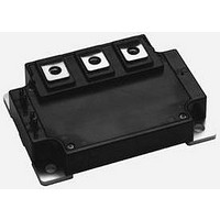
CM600DU-24NFH
Manufacturer Part Number
CM600DU-24NFH
Description
IGBT MOD DUAL 1200V 600A NFH SER
Manufacturer
Powerex Inc
Series
IGBTMOD™r
Type
IGBT Moduler
Datasheet
1.CM600DU-24NFH.pdf
(4 pages)
Specifications of CM600DU-24NFH
Configuration
Half Bridge
Voltage - Collector Emitter Breakdown (max)
1200V
Vce(on) (max) @ Vge, Ic
6.5V @ 15V, 600A
Current - Collector (ic) (max)
600A
Current - Collector Cutoff (max)
1mA
Input Capacitance (cies) @ Vce
95nF @ 10V
Power - Max
1550W
Input
Standard
Ntc Thermistor
No
Mounting Type
Chassis Mount
Package / Case
Module
Transistor Polarity
N Channel
Dc Collector Current
600A
Collector Emitter Voltage Vces
1.2kV
Power Dissipation Pd
1.55kW
Collector Emitter Voltage V(br)ceo
1.2kV
Prx Availability
RequestQuote
Distributorinventory
View
Voltage
1200V
Current
600A
Circuit Configuration
Dual
Rohs Compliant
Yes
Recommended Gate Driver
VLA502-01
Recommended Dc To Dc Converter
VLA502-01
Interface Circuit Ref Design
BG2A-NFH
Lead Free Status / RoHS Status
Lead free / RoHS Compliant
For Use With
BG2C-5015 - KIT DEV BOARD 5A FOR IGBTBG2C-3015 - KIT DEV BOARD 3A FOR IGBTBG2A-NFH - KIT DEV BOARD FOR IGBT
Igbt Type
-
Lead Free Status / RoHS Status
Lead free / RoHS Compliant, Lead free / RoHS Compliant
Available stocks
Company
Part Number
Manufacturer
Quantity
Price

Part Number:
CM600DU-24NFH
Manufacturer:
MITSUBISHI/三菱
Quantity:
20 000
Part Number:
CM600DU-24NFH
Quantity:
55


Powerex, Inc., 200 E. Hillis Street, Youngwood, Pennsylvania 15697-1800 (724) 925-7272
CM600DU-24NFH
Dual IGBTMOD™ NFH-Series Module
600 Amperes/1200 Volts
Thermal and Mechanical Characteristics, T j = 25 °C unless otherwise specified
Characteristics
Thermal Resistance, Junction to Case
Thermal Resistance, Junction to Case
Thermal Resistance, Junction to Case
Thermal Resistance, Junction to Case
Contact Thermal Resistance
External Gate Resistance
Rev. 09/08
1200
1000
800
600
400
200
10
0
8
6
4
2
0
SATURATION VOLTAGE CHARACTERISTICS
0
6
T
COLLECTOR-EMITTER VOLTAGE, V
T
j
j
= 25
= 25
GATE-EMITTER VOLTAGE, V
8
OUTPUT CHARACTERISTICS
o
2
o
C
C
COLLECTOR-EMITTER
10
(TYPICAL)
(TYPICAL)
12
4
V
GE
= 20V
14
15
6
I
I
I
C
C
C
= 1200A
= 600A
= 240A
GE
16
, (VOLTS)
CE
, (VOLTS)
8
14
13
12
11
10
18
9
8
10
20
R th(j-c) 'Q
R th(j-c) 'D
R th(j-c) Q
R th(j-c) D
R th(c-f)
Symbol
R G
1200
1000
800
600
400
200
10
10
10
10
0
4
3
2
1
0
0
EMITTER-COLLECTOR VOLTAGE, V
V
GE
Per 1/2 Module, Thermal Grease Applied
GATE-EMITTER VOLTAGE, V
TRANSFER CHARACTERISTICS
FORWARD CHARACTERISTICS
Per FWDi 1/2 Module, T C Reference
Per FWDi 1/2 Module, T C Reference
1
= 10V
Per IGBT 1/2 Module, T C Reference
T
T
T
T
j
j
j
j
T C Reference Point Under Chips
T C Reference Point Under Chips
= 25
= 125
5
= 25
= 125
FREE-WHEEL DIODE
Point per Outline Drawing
Point per Outline Drawing
o
o
C
C
o
o
Per IGBT 1/2 Module,
(TYPICAL)
C
(TYPICAL)
C
2
10
Test Conditions
3
GE
, (VOLTS)
15
EC
4
, (VOLTS)
20
5
10
10
10
10
10
-1
9
8
7
6
5
4
3
2
1
0
3
2
1
0
10
SATURATION VOLTAGE CHARACTERISTICS
0
Min.
0.52
-1
COLLECTOR-EMITTER VOLTAGE, V
—
—
—
—
—
V
V
GE
GE
COLLECTOR-CURRENT, I
200
= 0V
= 15V
T
T
j
j
CAPACITANCE VS. V CE
COLLECTOR-EMITTER
= 25
= 125
400
10
0.02
Typ.
o
—
—
—
—
—
C
o
0
(TYPICAL)
C
(TYPICAL)
600
0.083
0.034
Max.
0.15
0.06
800 1000
C
5.2
10
—
, (AMPERES)
1
C
C
C
CE
oes
ies
res
, (VOLTS)
°C/W
°C/W
°C/W
°C/W
°C/W
Units
1200
Ω
10
2
3
Related parts for CM600DU-24NFH
Image
Part Number
Description
Manufacturer
Datasheet
Request
R

Part Number:
Description:
IGBT MOD DUAL 1200V 600A NF SER
Manufacturer:
Powerex Inc
Datasheet:

Part Number:
Description:
IGBT Module
Manufacturer:
Powerex Inc
Datasheet:
Part Number:
Description:
IGBT MODULE NFH-SERIES HI-FREQUENCY DUAL DP 600 600
Manufacturer:
Powerex Inc
Datasheet:
Part Number:
Description:
TRANSISTOR,IGBT POWER MODULE,HALF BRIDGE,1.2kV V(BR)CES,600A I(C)
Manufacturer:
Powerex Inc
Datasheet:
Part Number:
Description:
Manufacturer:
Powerex Inc
Datasheet:
Part Number:
Description:
Manufacturer:
Powerex Inc
Datasheet:
Part Number:
Description:
Manufacturer:
Powerex Inc
Datasheet:
Part Number:
Description:
Manufacturer:
Powerex Inc
Datasheet:
Part Number:
Description:
Manufacturer:
Powerex Inc
Datasheet:
Part Number:
Description:
Manufacturer:
Powerex Inc
Datasheet:
Part Number:
Description:
Manufacturer:
Powerex Inc
Datasheet:
Part Number:
Description:
Manufacturer:
Powerex Inc
Datasheet:
Part Number:
Description:
Manufacturer:
Powerex Inc
Datasheet:
Part Number:
Description:
Manufacturer:
Powerex Inc
Datasheet:
Part Number:
Description:
Manufacturer:
Powerex Inc
Datasheet: