CM450DX-24S Powerex Inc, CM450DX-24S Datasheet - Page 2
CM450DX-24S
Manufacturer Part Number
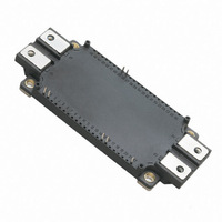
CM450DX-24S
Description
IGBT MOD DUAL 1200V 450A NX SER
Manufacturer
Powerex Inc
Series
IGBTMOD™r
Type
Dualr
Datasheet
1.CM450DX-24S.pdf
(6 pages)
Specifications of CM450DX-24S
Featured Product
6th Generation NX-S Series IGBTs
Configuration
Half Bridge
Voltage - Collector Emitter Breakdown (max)
1200V
Vce(on) (max) @ Vge, Ic
2.15V @ 15V, 450A
Current - Collector (ic) (max)
450A
Current - Collector Cutoff (max)
1mA
Input Capacitance (cies) @ Vce
45nF @ 10V
Power - Max
3400W
Input
Standard
Ntc Thermistor
Yes
Mounting Type
Chassis Mount
Package / Case
Module
Module Configuration
Dual
Dc Collector Current
450A
Collector Emitter Voltage Vces
1.2kV
Power Dissipation Pd
3.4W
Operating Temperature Range
-40°C To +150°C
Peak Reflow Compatible (260 C)
Yes
Rohs Compliant
Yes
Leaded Process Compatible
Yes
Prx Availability
RequestQuote
Distributorinventory
View
Voltage
1200V
Current
450A
Circuit Configuration
Dual
Recommended Gate Driver
VLA503-01
Recommended Dc To Dc Converter
VLA106-15242
Interface Circuit Ref Design
VLA536-01R
Lead Free Status / RoHS Status
Lead free / RoHS Compliant
Igbt Type
-
Lead Free Status / RoHS Status
Lead free / RoHS Compliant
Other names
835-1125
Available stocks
Company
Part Number
Manufacturer
Quantity
Price
Company:

Part Number:
CM450DX-24S
Manufacturer:
artesyn
Quantity:
1 000
Part Number:
CM450DX-24S
Manufacturer:
MIT
Quantity:
20 000


2
Powerex, Inc., 173 Pavilion Lane, Youngwood, Pennsylvania 15697 (724) 925-7272 www.pwrx.com
CM450DX-24S
Dual IGBTMOD™ NX-S Series Module
450 Amperes/1200 Volts
Absolute Maximum Ratings, T
Characteristics
Maximum Junction Temperature
Operating Power Device Junction Temperature
Storage Temperature
Mounting Torque, M5 Mounting Screws
Mounting Torque, M6 Main Terminal Screws
Module Weight (Typical)
Isolation Voltage (Terminals to Baseplate, f = 60Hz, AC 1 minute)
Inverter Sector
Collector-Emitter Voltage (V
Gate-Emitter Voltage (V
Collector Current (DC, T
Collector Current (Pulse)
Total Power Dissipation (T
Emitter Current, Free Wheeling Diode Forward Current (T
Emitter Current, Free Wheeling Diode Forward Current (Pulse)
*1 Case temperature (T
*3 Represent ratings and characteristics of the anti-parallel, emitter-to-collector free wheeling diode (FWDi).
*4 Pulse width and repetition rate should be such that device junction temperature (T
*5 Junction temperature (T
C
) and heatsink temperature (T
j
) should not increase beyond maximum junction temperature (T
CE
C
*4
= 119°C)
C
= 0V)
GE
= 25°C)
= 0V)
*1,*5
*1,*5
j
f
= 25°C unless otherwise specified
) measured point is just under the chips.
C
= 25°C)
*4
j
) does not exceed T
*1,*5
j(max)
) rating.
j(max)
rating.
Symbol
T
I
T
V
V
ERM
I
V
j(max)
T
CRM
P
I
j(op)
CES
GES
—
—
—
E
ISO
I
stg
C
tot
*3
*3
CM450DX-24S
-40 to 150
-40 to 125
+175
2500
1200
3400
330
±20
450
900
450
900
31
40
Amperes
Amperes
Amperes
Amperes
04/10 Rev. 0
Grams
Watts
Units
V
Volts
Volts
in-lb
in-lb
°C
°C
°C
rms
Related parts for CM450DX-24S
Image
Part Number
Description
Manufacturer
Datasheet
Request
R

Part Number:
Description:
IGBT MOD DUAL 1200V 450A NX SER
Manufacturer:
Powerex Inc
Datasheet:

Part Number:
Description:
Lamps DISC BY CML 2/99
Manufacturer:
CHICAGO MINIATURE LIGHTING, LLC
Datasheet:

Part Number:
Description:
NPN SILICON RF POWER TRANSISTOR
Manufacturer:
Advanced Semiconductor, Inc.

Part Number:
Description:
INDUCTOR CHIP SMD
Manufacturer:
Bourns Inc.
Datasheet:
Part Number:
Description:
INDUCTOR CHIP SMD
Manufacturer:
Bourns Inc.
Datasheet:

Part Number:
Description:
INDUCTOR CHIP SMD
Manufacturer:
Bourns Inc.
Datasheet:
Part Number:
Description:
INDUCTOR CHIP SMD
Manufacturer:
Bourns Inc.
Datasheet:
Part Number:
Description:
INDUCTOR CHIP SMD
Manufacturer:
Bourns Inc.
Datasheet:

Part Number:
Description:
INDUCTOR CHIP SMD
Manufacturer:
Bourns Inc.
Datasheet:
Part Number:
Description:
INDUCTOR CHIP SMD
Manufacturer:
Bourns Inc.
Datasheet:

Part Number:
Description:
Manufacturer:
Powerex Inc
Datasheet:
Part Number:
Description:
Manufacturer:
Powerex Inc
Datasheet:
Part Number:
Description:
Manufacturer:
Powerex Inc
Datasheet:
Part Number:
Description:
Manufacturer:
Powerex Inc
Datasheet:
Part Number:
Description:
Manufacturer:
Powerex Inc
Datasheet: