T40HFL60S02 Vishay, T40HFL60S02 Datasheet - Page 3
T40HFL60S02
Manufacturer Part Number
T40HFL60S02
Description
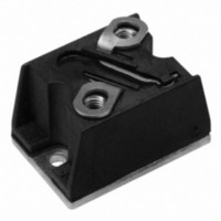
DIODE FAST REC 600V 40A D-55
Manufacturer
Vishay
Datasheet
1.T40HFL20S02.pdf
(15 pages)
Specifications of T40HFL60S02
Current - Reverse Leakage @ Vr
100µA @ 600V
Current - Average Rectified (io) (per Diode)
40A
Voltage - Dc Reverse (vr) (max)
600V
Reverse Recovery Time (trr)
200ns
Diode Type
Standard
Speed
Fast Recovery =< 500ns, > 200mA (Io)
Diode Configuration
Single
Mounting Type
Chassis Mount
Package / Case
D-55
Product
Fast Recovery Rectifier
Configuration
Single
Reverse Voltage
600 V
Forward Voltage Drop
1.6 V
Recovery Time
200 ns
Forward Continuous Current
40 A
Max Surge Current
500 A
Reverse Current Ir
100 uA
Mounting Style
Screw
Maximum Operating Temperature
+ 125 C
Minimum Operating Temperature
- 40 C
No. Of Phases
Single
Repetitive Reverse Voltage Vrrm Max
600V
Forward Current If(av)
40A
Forward Voltage Vf Max
1.6V
Module Configuration
Single
Peak Reflow Compatible (260 C)
Yes
Lead Free Status / RoHS Status
Lead free / RoHS Compliant
Voltage - Forward (vf) (max) @ If
-
Lead Free Status / RoHS Status
Lead free / RoHS Compliant, Lead free / RoHS Compliant
Other names
*T40HFL60S02


Note
(1)
Note
(1)
Note
• The table above shows the increment of thermal resistance R
Document Number: 93184
Revision: 19-May-10
REVERSE RECOVERY CHARACTERISTICS
PARAMETER
Maximum reverse
recovery time
Maximum reverse
recovery charge
BLOCKING
PARAMETER
Maximum peak reverse leakage current
RMS isolation voltage
THERMAL AND MECHANICAL SPECIFICATIONS
PARAMETER
Junction operating temperature range
Storage temperature range
Maximum internal thermal resistance,
junction to case per module
Thermal resistance,
case to heatsink per module
Mounting torque ± 10 %
Approximate weight
Case style
ΔR CONDUCTION
DEVICES
T40HFL
T70HFL
T85HFL
Tested on LEM 300 A diodemeter tester
A mounting compound is recommended and the torque should be rechecked after a period of about 3 hours to allow for the spread of
the compound
SYMBOL
SINUSOIDAL CONDUCTION AT T
180°
0.06
0.05
0.04
Q
t
rr
rr
DiodesAmericas@vishay.com, DiodesAsia@vishay.com,
busbar to terminal
For technical questions within your region, please contact one of the following:
base to heatsink
T
I
T
I
T
I
T
I
F
FM
F
FM
J
J
J
J
120°
0.08
0.06
0.05
= 1 A to V
= 1 A to V
= 25 °C, -dI
= 25 °C, -dI
= 25 °C, -dI
= 25 °C, -dI
TEST CONDITIONS
= π x rated I
= π x rated I
R
R
0.10
0.08
0.06
90°
= 30 V
= 30 V
F
F
F
F
(T-Modules), 40 A/70 A/85 A
F(AV)
F(AV)
/dt = 100 A/μs
/dt = 25 A/μs
/dt = 100 A/μs
/dt = 25 A/μs
SYMBOL
SYMBOL
, V
, V
Fast Recovery Diodes
V
R
R
I
T
RRM
ISOL
T
thJC
thCS
R
R
Stg
J
= - 30 V
= - 30 V
0.14
0.11
0.09
60°
(1)
J
MAXIMUM
thJC
T
50 Hz, circuit to base, all terminals
shorted, T
DC operation
Mounting surface, flat, smooth
and greased
M3.5 mounting screws
Non-lubricated threads
M5 screws terminals
Non-lubricated threads
See dimensions -
link at the end of datasheet
J
= 125 °C
0.25
0.55
S02
200
when devices operate at different conduction angles than DC
70
0.24
0.19
0.15
30°
TEST CONDITIONS
TEST CONDITIONS
T40HFL, T70HFL, T85HFL Series
T40HFL
J
S05
110
500
0.4
2.0
= 25 °C, t = 1 s
RECTANGULAR CONDUCTION AT T
180°
0.05
0.04
0.03
1000
1.35
S10
270
8.0
DiodesEurope@vishay.com
(1)
0.25
S02
200
0.6
70
120°
0.08
0.06
0.05
T70HFL
S05
110
500
0.4
2.1
Vishay Semiconductors
0.10
0.08
0.07
T40HFL T70HFL T85HFL
T40HFL T70HFL T85HFL
90°
0.85
1000
1.35
S10
270
8.5
- 40 to 125
- 40 to 150
1.3 ± 10 %
3 ± 10 %
S02
200
0.3
0.8
0.15
0.12
0.09
80
D-55 (T-module)
60°
3500
0.53
0.2
20
54
19
J
T85HFL
MAXIMUM
S05
120
500
0.6
3.5
0.015
0.24
0.19
0.46
30°
www.vishay.com
1000
S10
290
1.6
1.5
UNITS
UNITS
UNITS
UNITS
K/W
K/W
Nm
mA
oz.
°C
μC
V
ns
g
3
Related parts for T40HFL60S02
Image
Part Number
Description
Manufacturer
Datasheet
Request
R

Part Number:
Description:
357-036-542-201 CARDEDGE 36POS DL .156 BLK LOPRO
Manufacturer:
Vishay
Datasheet:
Part Number:
Description:
357-036-542-201 CARDEDGE 36POS DL .156 BLK LOPRO
Manufacturer:
Vishay
Datasheet:
Part Number:
Description:
357-036-542-201 CARDEDGE 36POS DL .156 BLK LOPRO
Manufacturer:
Vishay
Datasheet:
Part Number:
Description:
357-036-542-201 CARDEDGE 36POS DL .156 BLK LOPRO
Manufacturer:
Vishay
Datasheet:
Part Number:
Description:
357-036-542-201 CARDEDGE 36POS DL .156 BLK LOPRO
Manufacturer:
Vishay
Datasheet:
Part Number:
Description:
357-036-542-201 CARDEDGE 36POS DL .156 BLK LOPRO
Manufacturer:
Vishay
Datasheet:
Part Number:
Description:
357-036-542-201 CARDEDGE 36POS DL .156 BLK LOPRO
Manufacturer:
Vishay
Datasheet:
Part Number:
Description:
357-036-542-201 CARDEDGE 36POS DL .156 BLK LOPRO
Manufacturer:
Vishay
Datasheet:
Part Number:
Description:
357-036-542-201 CARDEDGE 36POS DL .156 BLK LOPRO
Manufacturer:
Vishay
Datasheet:
Part Number:
Description:
357-036-542-201 CARDEDGE 36POS DL .156 BLK LOPRO
Manufacturer:
Vishay
Datasheet:
Part Number:
Description:
357-036-542-201 CARDEDGE 36POS DL .156 BLK LOPRO
Manufacturer:
Vishay
Datasheet:
Part Number:
Description:
357-036-542-201 CARDEDGE 36POS DL .156 BLK LOPRO
Manufacturer:
Vishay
Datasheet:
Part Number:
Description:
357-036-542-201 CARDEDGE 36POS DL .156 BLK LOPRO
Manufacturer:
Vishay
Datasheet:
Part Number:
Description:
357-036-542-201 CARDEDGE 36POS DL .156 BLK LOPRO
Manufacturer:
Vishay
Datasheet:
Part Number:
Description:
357-036-542-201 CARDEDGE 36POS DL .156 BLK LOPRO
Manufacturer:
Vishay
Datasheet: