VBO125-12NO7 IXYS, VBO125-12NO7 Datasheet
VBO125-12NO7
Manufacturer Part Number
VBO125-12NO7
Description
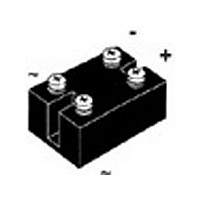
DIODE BRIDGE 124A 1200V PWS-C
Manufacturer
IXYS
Datasheet
1.VBO125-08NO7.pdf
(2 pages)
Specifications of VBO125-12NO7
Voltage - Peak Reverse (max)
1200V
Current - Dc Forward (if)
124A
Diode Type
Single Phase
Speed
Standard Recovery >500ns, > 200mA (Io)
Mounting Type
Chassis Mount
Package / Case
PWS-C
Phase Type
Single Phase
Number Of Elements
1
Peak Rep Rev Volt
1.2kV
Peak Non-repetitive Surge Current (max)
1950A
Avg. Forward Curr (max)
124A
Rev Curr
300uA
Forward Voltage
1.3V
Operating Temp Range
-40C to 150C
Pin Count
4
Mounting
Screw
Operating Temperature Classification
Automotive
Vrrm, (v)
1200
Vvrms, (v)
400
Idavm, (a)
124
@ Tc, (°c)
85
Ifsm, 10 Ms, Tvj = 45°c, (a)
1800
Vt0, (v)
0.80
Rt, (mohms)
3.0
Tvjm, (°c)
150
Rthjc, Per Chip, (k/w)
0.83
Rthjh, Per Chip, (k/w)
1.13
Package Style
PWS-C
Lead Free Status / RoHS Status
Lead free / RoHS Compliant
Reverse Recovery Time (trr)
-
Lead Free Status / Rohs Status
Compliant


Single Phase
Rectifier Bridge
1300
Symbol
I
I
I
T
T
T
V
M
Weight
Symbol
I
V
V
r
R
R
Data according to IEC 60747 refer to a single diode unless otherwise stated.
IXYS reserves the right to change limits, test conditions and dimensions.
© 2010 IXYS All rights reserved
1700
V
dAVM
FSM
2
R
T
t
VJ
stg
VJM
ISOL
F
T0
900
thJC
thJK
d
V
RSM
1200
1600
V
800
RRM
V
Conditions
T
T
V
T
V
T
V
T
V
50/60 Hz, RMS
I
Mounting torque (M5)
Terminal connection torque (M5)
typ.
Conditions
V
V
I
For power-loss calculations only
T
per diode; 180°
per module; 180°
per diode; 180°
per module; 180°
ISOL
F
C
VJ
VJ
VJ
VJ
VJ
R
R
R
R
R
R
= 150 A;
= 85°C, module
= 0
= 0
= 0
= 0
= V
= V
= 45°C;
= T
= 45°C
= T
= T
≤ 1 mA
RRM
RRM
VJM
VJM
VJM
Type
VBO 125-08NO7
VBO 125-12NO7
VBO 125-16NO7
;
;
t = 10 ms (50 Hz), sine
t = 8.3 ms (60 Hz), sine
t = 10 ms (50 Hz), sine
t = 8.3 ms (60 Hz), sine
t = 10 ms (50 Hz), sine
t = 8.3 ms (60 Hz), sine
t = 10 ms (50 Hz), sine
t = 8.3 ms (60 Hz), sine
t = 1 min
t = 1 s
T
T
T
VJ
VJ
VJ
= 25°C
= T
= 25°C
VJM
Characteristic Values
≤
≤
≤
Maximum Ratings
-40...+150
-40...+150
44 ±15%
44 ±15%
5 ±15%
5 ±15%
16200
16000
12800
13600
0.138
0.188
1800
1950
1600
1800
2500
3000
0.83
1.13
124
150
225
0.3
8.0
1.3
0.8
3
~
~
+
–
lb.in.
lb.in.
K/W
K/W
K/W
K/W
mΩ
Nm
Nm
A
A
A
A
mA
mA
V~
V~
°C
°C
°C
2
2
2
2
A
A
A
A
A
V
V
g
s
s
s
s
I
V
Features
• Package with screw terminals
• Isolation voltage 3000 V~
• Planar passivated chips
• Blocking voltage up to 1800 V
• Low forward voltage drop
• UL registered E 72873
Applications
• Supplies for DC power equipment
• Input rectifiers for PWM inverter
• Battery DC power supplies
• Field supply for DC motors
Advantages
• Easy to mount with two screws
• Space and weight savings
• Improved temperature and power cycling
Dimensions in mm (1 mm = 0.0394")
dAVM
RRM
=
= 800-1600 V
VBO 125
124 A
20100706a
1 - 2
Related parts for VBO125-12NO7
Image
Part Number
Description
Manufacturer
Datasheet
Request
R

Part Number:
Description:
DIODE BRIDGE 124A 1400V PWS-C
Manufacturer:
IXYS
Datasheet:
Part Number:
Description:
DIODE BRIDGE 124A 1800V PWS-C
Manufacturer:
IXYS
Datasheet:

Part Number:
Description:
DIODE BRIDGE 124A 800V PWS-C
Manufacturer:
IXYS
Datasheet:
Part Number:
Description:
DIODE BRIDGE 124A 1600V PWS-C
Manufacturer:
IXYS
Datasheet:

Part Number:
Description:
HiPerFET Power MOSFETs
Manufacturer:
IXYS Corporation
Datasheet:
Part Number:
Description:
J-K-Type Flip-Flop
Manufacturer:
IXYS Corporation
Datasheet:
Part Number:
Description:
HiPerRF Power MOSFETs
Manufacturer:
IXYS Corporation
Datasheet:
Part Number:
Description:
Rectifier Module for Three Phase Power Factor Correction
Manufacturer:
IXYS Corporation
Datasheet:
Part Number:
Description:
Thyristor Modules Thyristor/Diode Modules
Manufacturer:
IXYS Corporation
Datasheet:
Part Number:
Description:
Thyristor Modules Thyristor/Diode Modules
Manufacturer:
IXYS Corporation
Datasheet:
VBO125-12NO7 Summary of contents
Page 1
... R per diode; 180° thJK per module; 180° Data according to IEC 60747 refer to a single diode unless otherwise stated. IXYS reserves the right to change limits, test conditions and dimensions. © 2010 IXYS All rights reserved Maximum Ratings 124 1800 1950 ...
Page 2
... Fig. 4 Power dissipation versus direct output current and ambient temperature 1.5 K 0.01 0.1 t[s] Fig. 6 Transient thermal impedance per diode/thyristor, calculated IXYS reserves the right to change limits, test conditions and dimensions. © 2010 IXYS All rights reserved I F(OV) ------ I FSM I (A) FSM TVJ=45°C TVJ=150°C 1 ...