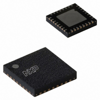
PN5120A0HN1/C1,151 NXP Semiconductors, PN5120A0HN1/C1,151 Datasheet - Page 13

PN5120A0HN1/C1,151
Manufacturer Part Number
PN5120A0HN1/C1,151
Description
IC TRANSMISSION MOD 32-HVQFN
Manufacturer
NXP Semiconductors
Datasheet
1.PN5120A0HN1C1118.pdf
(23 pages)
Specifications of PN5120A0HN1/C1,151
Package / Case
32-VQFN Exposed Pad, 32-HVQFN, 32-SQFN, 32-DHVQFN
Rf Type
Read / Write
Frequency
13.56MHz
Features
ISO14443A, ISO1443B
Operating Frequency
13.56 MHz
Supply Voltage (max)
3.6 V
Supply Voltage (min)
2.5 V
Supply Current
7 mA
Maximum Power Dissipation
200 mW
Operating Temperature Range
- 30 C to + 85 C
Maximum Operating Temperature
+ 85 C
Minimum Operating Temperature
- 30 C
Mounting Style
SMD/SMT
Lead Free Status / RoHS Status
Lead free / RoHS Compliant
Lead Free Status / RoHS Status
Lead free / RoHS Compliant, Lead free / RoHS Compliant
Other names
935280537151
PN5120A0HN1/C1-S
PN5120A0HN1/C1-S
PN5120A0HN1/C1-S
PN5120A0HN1/C1-S
NXP Semiconductors
124533
Product short data sheet
8.1.3 ISO 14443B reader/writer functionality
8.2 NFCIP-1 mode
The international standard ISO 14443 standard covers 2 communication schemes: the
ISO 14443-A and the ISO 14443B.
The PN512 reader IC fully supports the ISO 14443.
The following registers and bits cover the ISO 14443B communication scheme:
As a reference documentation the international standard ISO 14443 'Identification cards-
Contactless integrated circuit(s) cards- Proximity cards, part 1-4' can be taken.
Note: NXP Semiconductors does not offer a software library to design in the ISO 14443B
protocol.
The NFCIP-1 communication differentiates between an active and a Passive
Communication mode.
In order to fully support the NFCIP-1 standard the PN512 supports the Active and Passive
Communication mode at the transfer speeds 106 kbit/s, 212 kbit/s and 424 kbit/s as
defined in the NFCIP-1 standard.
Fig 8. NFCIP-1 mode
•
•
•
•
Active Communication mode means both the initiator and the target are using their
own RF field to transmit data.
Passive Communication mode means that the target answers to an initiator command
in a load modulation scheme. The initiator is active in terms of generating the RF field.
Initiator: generates RF field at 13.56 MHz and starts the NFCIP-1 communication
Target: responds to initiator command either in a load modulation scheme in Passive
Communication mode or using a self generated and self modulated RF field for Active
Communication mode.
Battery
Initiator:Active
PN512
Rev. 3.3 — 13 June 2007
PN512
Transmission Module
Passive or
Target:
© NXP B.V. 2007. All rights reserved.
Active
PN512
Battery
µC
13 of 23


