EVB90109 Melexis Inc, EVB90109 Datasheet
EVB90109
Specifications of EVB90109


Related parts for EVB90109


EVB90109 Summary of contents
Page 1
... Two extra pins have been added for extended control options on the voltage on the MODU pin. The EVB90109 can be used as a 125 kHz reader, to read out the load modulation from a transponder. It can also be used to send information to a transponder using On/Off keying modulation. For fast protocol which required fast fall time on the reader’ ...
Page 2
... NTENNA VOLTAGE IN READ OPERATION 2.5 N OISE CANCELLATION IN READ OPERATION 2.6 A 100% NTENNA VOLTAGE IN MODULATION OPERATION 2.7 F .............................................................................................................................. 6 AST DECAY CIRCUIT 3 SCHEMATIC................................................................................................................................................................................ 7 4 PHYSICAL OUTLINE ................................................................................................................................................................... 8 5 PINNING OF THE EVB90109 ....................................................................................................................................................... 9 6 COMPONENTS............................................................................................................................................................................ 9 7 DISCLAIMER..............................................................................................................................................................................10 390129010901 Rev 005 MLX90109 Evaluation Board ................................................................................................... 4 ............................................................................................... 5 ............................................................................... 5 Page EVB90109 Evaluation Board ...
Page 3
... Description 2.1 General explanation The EVB90109 consists of a single chip inductive RFID reader for the 125 kHz frequency range with an external inductance (L) and capacitance (C) connected as a parallel resonant circuit. The antenna voltage amplitude can be set On/Off externally with the digital line MODUR2, which controls a resistive and capacitive network called “ ...
Page 4
... V The EVB90109 is provided with two resistors R1 and R2 as the modulation netwok controlled through the pin MODUR2 to set the voltage on the antenna respectively On (Vmodu to 0.8 Volts) and Off (Vmodu to 5 Volts). Others footprint C1, C3 and R3 and an extra pin MODUR3 are available on the board and can be used for specific applications ...
Page 5
... Switching ON the magnetic field depends on the internal driver of MLX90109 and takes less than 5 carrier periods. Switching OFF the magnetic field depend on the quality factor (Qant) of the parallel antenna connected to the reader (about 24 periods with the EVB90109). To reduce this fall time, the “fast decay” circuit can be used. ...
Page 6
... Very small fall time may be required in fast protocol understood by the transponder in the field. This is why, the EVB90109 include a “fast decay” circuit controlled through the pin FAST_DECAY and composed of the transitstor Q1 and the diode D1. The following picture shows how to implement the “fast decay” system. ...
Page 7
... Schematic The following diagram shows the schematic of the EVB90109. All components in grey are not mounted but the footprints are present if the user wants to use it for dedicated applications. VDD C1 R1 COIL VSS SPEED 390129010901 Rev 005 MLX90109 Evaluation Board MODUR3 5 MODUR2 6 Figure 2: Schematic of the EVB90109 ...
Page 8
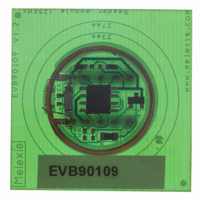
... Physical outline The following figure shows the outline of the MLX90109 evaluation board. 390129010901 Rev 005 MLX90109 Evaluation Board Coil DIL-10 DIL- MLX90109 Figure 3: EVB90109 outline: top side Page EVB90109 Evaluation Board Aug-2005 ...
Page 9
... Fast decay circuit control Modulation Network Modulation Network Decoding selection Clock signal Decoded data Power Supply Table 2: Pinning of the EVB90109 Description Modulation network Modulation network Additional resistor for the modulation network Noise cancellation capacitance Additional capacitance for the modulation network Additional capacitance for the modulation network ...
Page 10
... For the latest version of this document our website at Or for additional information contact Melexis Direct: Europe and Japan: Phone: +32 1367 0495 E-mail: sales_europe@melexis.com 390129010901 Rev 005 MLX90109 Evaluation Board www.melexis.com All other locations: Phone: +1 603 223 2362 E-mail: sales_usa@melexis.com ISO/TS 16949 and ISO14001 Certified Page EVB90109 Evaluation Board Aug-2005 ...