TMEB8704 Atmel, TMEB8704 Datasheet - Page 4
TMEB8704
Manufacturer Part Number
TMEB8704
Description
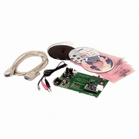
KIT DEMO FOR RFID TRANSPONDERS
Manufacturer
Atmel
Type
Development kitr
Datasheet
1.TMEB8704.pdf
(27 pages)
Specifications of TMEB8704
Contents
Board, Cables, Manual and more
For Use With/related Products
e5530, T5552, T5557, TK5530, TK5551, TK5552, U2270B
Lead Free Status / RoHS Status
Contains lead / RoHS non-compliant


3. Description of the Application Board System
3.1
3.2
3.3
3.3.1
4
System Overview
Power Supply
Antenna Interface
TMEB8704 Application Note
Frequency Tuning Mode Selection
The RFID application board consists of a standard microcontroller board 1.0 (equipped with the
Atmel microcontroller AT90S8515), combined with a piggybacked board serving as antenna
interface.
The microcontroller AT90S8515 carries out the following functions:
The application software is downloaded into the 8 KByte Flash memory of the microcontroller.
The current program version is indicated on the label attached to the main board.
For proper operation of the application board, an external power supply in the range of DC 10V
to 15V/200 mA is required. A bridge rectifier placed at the connector input is used for polarity
independence.
The antenna interface (see
on the main board. The LED Power indicates the actual supply voltage. To adapt a specific
antenna coil to the resonant frequency and the Q-factor, the components CANT1/CANT2 and
R14 (see
added coil. The parameters and the corresponding components for the adjustment are given as
follows:
Resonant frequency: f
Q-factor:
The application system has a built-in tuning feature to match the resonant frequency of the LC
antenna circuit automatically to the frequency of a specific transponder. The board is equipped
with two stages of high-voltage transistor switches to tune the resonator by switched capacitors.
This increases the reliability and operating distance.
The frequency tuning can be selected using jumper J3 (see
• Handling the bi-directional data communication between the application board and the host
• Executing the read and write commands to be sent to the antenna interface
• Decoding the specific read data delivered by the antenna interface
PC
Figure 2-2 on page
res
Q = 20 by R14
= 125 kHz by CANT1/CANT2 at Jumper 3 to position Disable
Figure 2-2 on page
3) can be changed. The matching of the interface depends on the
3) is connected via the header connector located
Figure 2-2 on page
3).
4781A–RFID–10/05
Related parts for TMEB8704
Image
Part Number
Description
Manufacturer
Datasheet
Request
R

Part Number:
Description:
DEV KIT FOR AVR/AVR32
Manufacturer:
Atmel
Datasheet:

Part Number:
Description:
INTERVAL AND WIPE/WASH WIPER CONTROL IC WITH DELAY
Manufacturer:
ATMEL Corporation
Datasheet:
Part Number:
Description:
Low-Voltage Voice-Switched IC for Hands-Free Operation
Manufacturer:
ATMEL Corporation
Datasheet:
Part Number:
Description:
MONOLITHIC INTEGRATED FEATUREPHONE CIRCUIT
Manufacturer:
ATMEL Corporation
Datasheet:
Part Number:
Description:
AM-FM Receiver IC U4255BM-M
Manufacturer:
ATMEL Corporation
Datasheet:
Part Number:
Description:
Monolithic Integrated Feature Phone Circuit
Manufacturer:
ATMEL Corporation
Datasheet:
Part Number:
Description:
Multistandard Video-IF and Quasi Parallel Sound Processing
Manufacturer:
ATMEL Corporation
Datasheet:
Part Number:
Description:
High-performance EE PLD
Manufacturer:
ATMEL Corporation
Datasheet:
Part Number:
Description:
8-bit Flash Microcontroller
Manufacturer:
ATMEL Corporation
Datasheet:
Part Number:
Description:
2-Wire Serial EEPROM
Manufacturer:
ATMEL Corporation
Datasheet: