EVB90121 Melexis Inc, EVB90121 Datasheet
EVB90121
Specifications of EVB90121


Related parts for EVB90121


EVB90121 Summary of contents
Page 1
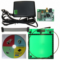
... Smart labels and write systems Access control systems General Description The EVB90121 is an assembled module that allows to evaluate the advantages of the MLX90121 13MHz transceiver IC and to facilitate the development of RFID applications. The board voltage is supplied by a jack connector from Volts DC. The internal power supply of the board can be chosen between 3 Volts and 5 Volts DC by putting the corresponding jumper up or down ...
Page 2
... Table of Contents 1 SCHEMATIC..................................................................................................................... 3 2 PHYSICAL OUTLINE ....................................................................................................... 4 3 COMPONENTS ................................................................................................................ 5 4 GUIDELINES .................................................................................................................... 6 4.1 P ........................................................................................................................6 OWER SUPPLY 4.2 A .............................................................................................................6 NTENNA CONNECTION 4.3 C ONNECTION TO A MICROCONTROLLER 4.4 D ................................................................................................................7 IGITAL CONNECTOR 4.5 A ................................................................................................................7 NALOGUE OUTPUTS 5 DISCLAIMER.................................................................................................................... 8 390129012101 Rev. 003 MLX90121 Evaluation Board ......................................................................................6 Page EVB90121 Evaluation Board Sept ...
Page 3
... Schematic The schematic if the MLX90121 evaluation board is shown in figure GND 2 GND 1 1 Figure 1: Schematic of the evaluation board EVB90121 390129012101 Rev. 003 MLX90121 Evaluation Board 2 Page EVB90121 1 Evaluation Board Sept ...
Page 4
... Physical outline Figures 2 and 3 show the outline of the MLX90121 evaluation board. Figure 2: MLX90121 evaluation board outline: top side Figure 3: MLX90121 evaluation board outline: bottom side 390129012101 Rev. 003 MLX90121 Evaluation Board Page EVB90121 Evaluation Board Sept ...
Page 5
... Components The table below gives an overview of all components that composed the evaluation board EVB90121. Reference Value R5,R6,R7,R8,R9 R10 CV1 5-50 pF C1,C2,C3,C6 10uF C8,C9,C12 100 nF C10,C11 22 pF D1,D2 - JP1 SMA connector JP2 DIL10 connector J1 Jack connector J2 Debug connector L1 VK200 L2 4,7 µH L3 5,6 µ ...
Page 6
... Guidelines This chapter describes all connections and jumpers available on the EVB90121 circuit to be able to use it in the most efficient way. 4.1 Power supply The circuit can be supplied with a standard DC supply block (transformer or switch mode power supplies) connected to the jack connector J1. The input supply can be selected from 6 to maximum 9 volts DC to avoid permanent damage of the evaluation board ...
Page 7
... Serial Clock Input MODE Configuration or Communication selection Input DIN Data Input DOUT Data Output RTB Reception or Transmission selection Input DSYNC Synchronization Output Table 3: Connector J2 Description Supply Voltage Antenna Ground Output XBUF of MLX90121 device Table 4: Test pins Page EVB90121 Evaluation Board Sept ...
Page 8
... Or for additional information contact Melexis Direct: Europe, Asia: Phone: +32 1367 0495 E-mail: sales_europe@melexis.com 390129012101 Rev. 003 MLX90121 Evaluation Board www.melexis.com Americas: Phone: +1 603 223 2362 E-mail: sales_usa@melexis.com ISO/TS 16949 and ISO14001 Certified Page EVB90121 Asia: Phone: +32 1367 0495 E-mail: sales_asia@melexis.com Evaluation Board Sept ...