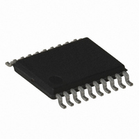
AT86RF401X-6GS Atmel, AT86RF401X-6GS Datasheet - Page 21

AT86RF401X-6GS
Manufacturer Part Number
AT86RF401X-6GS
Description
IC MICRO TRANSM RF W/AVR 20TSSOP
Manufacturer
Atmel
Datasheet
1.AT86RF401U-6GS.pdf
(52 pages)
Specifications of AT86RF401X-6GS
Frequency
264MHz ~ 456MHz
Applications
Garage Opener, RKE, Telemetry
Modulation Or Protocol
ASK, OOK
Data Rate - Maximum
10 kbps
Power - Output
6dBm
Current - Transmitting
23.2mA
Data Interface
PCB, Surface Mount
Antenna Connector
PCB, Surface Mount
Memory Size
1KB EEPROM, 1KB RAM
Voltage - Supply
2 V ~ 5 V
Operating Temperature
-40°C ~ 85°C
Package / Case
20-TSSOP
Lead Free Status / RoHS Status
Contains lead / RoHS non-compliant
Features
-
SRAM Data Memory
Program and Data
Addressing Modes
1424F–RKE–12/03
Figure 10 shows how the AT86RF401 SRAM memory is organized.
Figure 10. SRAM Organization
The lower 224 Data Memory locations address the Register File, the I/O Memory and
the internal data SRAM. The first 96 locations address the Register File + I/O Memory,
and the next 128 locations address the internal data SRAM.
The five different addressing modes for the data memory cover: Direct, Indirect with Dis-
placement, Indirect, Indirect with Pre-decrement, and Indirect with Post-increment. In
the register file, registers R26 to R31 feature the indirect addressing pointer registers.
The direct addressing reaches the entire data space.
The Indirect with Displacement mode features a 63 address locations reach from the
base address given by the Y or Z register.
When using register indirect addressing modes with automatic pre-decrement and post-
increment, the address registers X, Y and Z are decremented and incremented.
The 32 general-purpose working registers, 64 I/O registers and the 128 bytes of internal
data SRAM in the AT86RF401 are all accessible through all these addressing modes.
The AT86RF401 AVR Enhanced RISC microcontroller supports powerful and efficient
addressing modes for access to the program memory (Flash) and data memory (SRAM,
Register File and I/O Memory). This section describes the different addressing modes
supported by the AVR architecture. In the figures, OP means the operation code part of
the instruction word. To simplify, not all figures show the exact location of the address-
ing bits.
I/O Registers
Register File
R29
R30
R31
$3D
$3E
$00
$01
$02
$3F
R0
R1
R2
...
...
Data Address Space
Internal SRAM
AT86RF401
$00DE
$00DF
$001D
$001E
$005D
$005E
$005F
$0000
$0001
$0002
$001F
$0020
$0021
$0022
$0060
$0061
...
...
...
21


