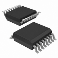
U2741B-NFBY Atmel, U2741B-NFBY Datasheet - Page 7

U2741B-NFBY
Manufacturer Part Number
U2741B-NFBY
Description
IC TRANSMITTR UHF ASK/FSK 16SO
Manufacturer
Atmel
Datasheet
1.U2741B-NFBY.pdf
(11 pages)
Specifications of U2741B-NFBY
Frequency
300MHz ~ 450MHz
Applications
General Purpose
Modulation Or Protocol
UHF, ASK, FSK
Data Rate - Maximum
20 kBaud
Power - Output
3dBm
Current - Transmitting
10mA
Data Interface
PCB, Surface Mount
Antenna Connector
PCB, Surface Mount
Voltage - Supply
2 V ~ 5.5 V
Operating Temperature
-40°C ~ 85°C
Package / Case
16-SSOP
Lead Free Status / RoHS Status
Lead free / RoHS Compliant
Features
-
Memory Size
-
6. Absolute Maximum Ratings
Stresses beyond those listed under “Absolute Maximum Ratings” may cause permanent damage to the device. This is a stress rating
only and functional operation of the device at these or any other conditions beyond those indicated in the operational sections of this
specification is not implied. Exposure to absolute maximum rating conditions for extended periods may affect device reliability.
7. Thermal Resistance
8. Electrical Characteristics
All parameters are referred to GND (pin 5). The possible operating ranges refer to different circuit conditions:
V
4733B–RKE–09/05
Parameters
Supply current (power down)
Supply current (power up, output OFF) V
Supply current (power up, output ON) V
Output power
Output power variation for the full
temperature range
Output power variation for
f = 315 MHz compared to
f = 433.92 MHz
Maximum peak output
antenna voltage
Spurious emission
Parameters
Supply voltage
Power dissipation
Junction temperature
Storage temperature
Ambient temperature
Parameters
Junction ambient
S
= 2.0V to 5.5V at T
amb
= –20°C to +70°C, V
Test Conditions
V
V
R
R
T
V
V
T
V
P
f = 315 MHz
P
at P
the load impedance must be selected to
meet the V
the supply current is not dependent on
the load impedance tolerance
at T
f
Load capacitance at CLK 3 pF
f = 230 MHz to 470 MHz
f < 230 MHz, f > 470 MHz
o
amb
amb
ASK
ASK
ASK
S
S
S
S
out
out
PWRSET
PWRSET
±(n
= 3V, T
= 3.0V
= 2.4V
= 2.0V
amb
out
= P
= P
, V
= –40°C to +85°C, f = 433.92 MHz,
= –20°C to +85°C, f = 433.92 MHz,
= GND, V
= V
S
= 2.0 mW,
FSK
= 25°C
= 2.2V to 5.5V at T
Ref
Ref
f
S
PC
= 1.2 k
= 1.8 k
, V
amb
+ P
+ P
out
) where f
S
0.3V, V
maximum requirement
= 25°C, f = 433.92 MHz
= 3V, R
FSK
Ref
Ref
Symbol
Symbol
R
= V
T
T
P
V
S
PC
amb
T
thJA
stg
tot
S
j
< 3.6V
PWRSET
S
= 6.78 MHz
, V
s
amb
= 3V
= 1.2 k
= –40°C to +85°C (typically 25°C, 3V)
Min.
–55
–40
Symbol
IS
V
IS
IS
P
P
outmax
transmit
Em
Em
P
P
P
P
Ref
Ref
off
on
Ref
Ref
Ref
Ref
Value
180
Min.
–0.5
1.5
Max.
250
150
125
105
6
V
S
Typ.
– 0.7V
4.7
1.5
10
3
1
Max.
0.35
12.5
–1.5
–4.0
–5.5
U2741B
–40
–58
6.2
5
3
Unit
Unit
K/W
mW
°C
°C
°C
V
V
dBm
dBm
Unit
dBC
dBC
mA
mA
(peak)
µA
dB
dB
dB
dB
7


