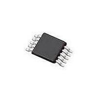
SI4010-C2-GT Silicon Laboratories Inc, SI4010-C2-GT Datasheet - Page 134

SI4010-C2-GT
Manufacturer Part Number
SI4010-C2-GT
Description
IC TX 27-960MHZ FSK 3.6V 10MSOP
Manufacturer
Silicon Laboratories Inc
Series
EZRadio®r
Type
Crystalless SoC RF Transmitterr
Datasheet
1.SI4010-C2-GT.pdf
(156 pages)
Specifications of SI4010-C2-GT
Package / Case
10-MSOP
Mfg Application Notes
SI4010 Calculator Spreadsheet AppNote
Frequency
27MHz ~ 960MHz
Applications
Garage Openers, RKE, Security Alarms
Modulation Or Protocol
FSK, OOK
Data Rate - Maximum
100 kBaud
Power - Output
10dBm
Current - Transmitting
19.8mA
Data Interface
PCB, Surface Mount
Antenna Connector
PCB, Surface Mount
Memory Size
4kB RAM
Features
8051 MCU Core, Crystal-less Operation
Voltage - Supply
1.8 V ~ 3.6 V
Operating Temperature
-40°C ~ 85°C
Operating Frequency
27 MHz to 960 MHz
Maximum Operating Temperature
+ 85 C
Mounting Style
SMD/SMT
Operating Supply Voltage
1.8 V to 3.6 V
Supply Current
14.2 mA
Lead Free Status / RoHS Status
Lead free / RoHS Compliant
Lead Free Status / RoHS Status
Lead free / RoHS Compliant, Lead free / RoHS Compliant
Other names
336-1997-5
Available stocks
Company
Part Number
Manufacturer
Quantity
Price
Part Number:
SI4010-C2-GT
Manufacturer:
SILICON LABS/芯科
Quantity:
20 000
Company:
Part Number:
SI4010-C2-GTR
Manufacturer:
ST
Quantity:
1 000
Part Number:
SI4010-C2-GTR
Manufacturer:
SILICON LABS/芯科
Quantity:
20 000
Si4010-C2
34.4. 8-Bit Timer/Timer Mode (Split Mode)
When TMR2SPLIT=1, the timer operates as two independent 8-bit timers. Each of the 8-bit timers can
independently operate in either 8-bit timer or 8-bit capture modes. The only common signals for both 8-bit
timers are capture event input signal and the interrupt output signal. Therefore, four possible configura-
tions are possible in split mode. All of them are described in the subsequent sections.
If TMR2L_CAP=0 and TMR2H_CAP=0, both halves operate as two independent 8-bit timers with indepen-
dently set clocks.
As the 8-bit timer register increments and overflows from 0xFF to 0x00, the 8-bit value in the time reload
registers (TMR2RH or TMR2RL) is loaded into the corresponding timer register (TMR2H or TMR2L), and
the corresponding byte overflow flag TMR2INTH or TMR2INTL are set, respectively. If timer interrupts are
enabled (see IE and EIE1 registers), an interrupt will be generated on each timer overflow.
134
INT1 for TMR3
rtc_pulse (100us)
rtc_tick (5.33us)
TMR_CLKSEL
clk_sys/12
clk_sys
INT0
Figure 34.3. Capture 16-bit Mode Block Diagram (Wide Mode)
0
1
2
3
2
TMR2L_RUN
Capture
TMR2RL
TMR2L
Rev. 1.0
TMR2RH
TMR2H
TMR2INTH
TMR2INTL
TMR2INTL_EN
TMR2SPLIT
TMR2H_CAP
TMR2L_CAP
TMR2H_RUN
TMR2L_RUN
Interrupt


