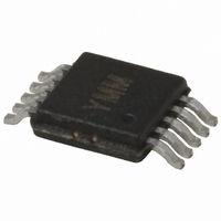
MICRF112YMM Micrel Inc, MICRF112YMM Datasheet - Page 15

MICRF112YMM
Manufacturer Part Number
MICRF112YMM
Description
IC XMITTER UHF ASK/FSK 10-MSOP
Manufacturer
Micrel Inc
Datasheet
1.MICRF112-433_EV.pdf
(20 pages)
Specifications of MICRF112YMM
Frequency
300MHz ~ 450MHz
Applications
RKE
Modulation Or Protocol
ASK, OOK
Data Rate - Maximum
50 kbps
Power - Output
10dBm
Current - Transmitting
12.3mA
Data Interface
PCB, Surface Mount
Antenna Connector
PCB, Surface Mount
Voltage - Supply
1.8 V ~ 3.6 V
Operating Temperature
-40°C ~ 125°C
Package / Case
10-MSOP, Micro10™, 10-uMAX, 10-uSOP
Transmitting Current
12.5mA
Data Rate
50Kbps
Frequency Range
300MHz To 450MHz
Modulation Type
ASK, FSK
Rf Ic Case Style
MSOP
No. Of Pins
10
Supply Voltage Range
1.8V To 3.6V
Operating
RoHS Compliant
Output Power
10dBm
Rohs Compliant
Yes
Lead Free Status / RoHS Status
Lead free / RoHS Compliant
Features
-
Memory Size
-
Lead Free Status / RoHS Status
Lead free / RoHS Compliant
Other names
576-1963-5
MICRF112YMM
MICRF112YMM
Available stocks
Company
Part Number
Manufacturer
Quantity
Price
Company:
Part Number:
MICRF112YMM
Manufacturer:
MICREL
Quantity:
700
Part Number:
MICRF112YMM
Manufacturer:
MICREL/麦瑞
Quantity:
20 000
Company:
Part Number:
MICRF112YMM-TR
Manufacturer:
TI
Quantity:
87
Output Matching Network
Part of the function of the output network is to attenuate
the second and third harmonics. When matching to a
transmit frequency, care must be taken not only to
optimize for maximum output power but to attenuate
unwanted harmonics.
Layout Issues
PCB Layout is of primary concern to achieve optimum
performance and consistent manufacturing results. Care
must used on orientation of components to ensure they
do not couple or decouple the RF signal. PCB trace
length should be short to minimize parasitic inductance,
(1 inch ~ 20nH). For example, depending on inductance
values, a 0.5 inch trace can change the inductance by as
Micrel, Inc.
March 2008
15
much as 10%. To reduce parasitic inductance, the use of
wide traces and a ground plane under signal traces is
recommended. Vias with low value inductance should be
used for components requiring a connection-to-ground.
Antenna Layout
Directivity is affected by antenna trace layout. No ground
plane should be under the antenna trace. For consistent
performance, components should not be placed inside
the loop of the antenna. Gerbers for Figure 7, with a
suggested layout, can be obtained on the Micrel web site
at: http://www.micrel.com.
(408) 944-0800
M9999-031008
MICRF112


