XBP24-DMUIT-250 Digi International, XBP24-DMUIT-250 Datasheet - Page 45
XBP24-DMUIT-250
Manufacturer Part Number
XBP24-DMUIT-250
Description
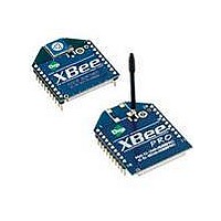
XBEE-PRO MESH 2.4 EXTENDED
Manufacturer
Digi International
Series
XBEE-PRO™r
Specifications of XBP24-DMUIT-250
Frequency
2.4GHz
Data Rate - Maximum
250kbps
Modulation Or Protocol
DSSS
Power - Output
18dBm
Sensitivity
-100dBm
Voltage - Supply
2.8 V ~ 3.4 V
Current - Receiving
55mA
Current - Transmitting
250mA
Data Interface
PCB, Through Hole
Antenna Connector
U.FL
Operating Temperature
-40°C ~ 85°C
Lead Free Status / RoHS Status
Lead free / RoHS Compliant
Package / Case
-
Applications
-
Memory Size
-
Lead Free Status / Rohs Status
Lead free / RoHS Compliant
Other names
Q4197953C


XBee/XBee‐PRO DigiMesh 2.4 RF Modules
API Identifier Value: (0x88)
Response to previous command.
In response to an AT Command message, the module will send an AT Command Response message. Some com-
mands will send back multiple frames (for example, the ND (Node Discover) command).
AT Command Response
A
P
I
P
a
c
k
e
t
Start Delimiter
Length
Frame-specific Data
Checksum
AT Command Response Frames.
© 2010 Digi International, Inc.
Frame Fields
Frame Type
Frame ID
AT Command
Command Status
Command Data
Offset Example
MSB 1 0x00
LSB 2 0x05
0 0x7E
3 0x88
4 0x01
5 ‘B’ = 0x42
6 ‘D’ = 0x44
7 0x00
8 0xF0
Number of bytes between the length and the checksum
Identifies the UART data frame being reported. Note: If
Frame ID = 0 in AT Command Mode, no AT Command
Response will be given.
Command Name - Two ASCII characters that identify the
AT Command.
0 = OK
1 = ERROR
2 = Invalid Command
3 = Invalid Parameter
Register data in binary format. If the register was set,
then this field is not returned, as in this example.
0xFF - the 8 bit sum of bytes from offset 3 to this byte.
Description
45
Related parts for XBP24-DMUIT-250
Image
Part Number
Description
Manufacturer
Datasheet
Request
R

Part Number:
Description:
MODULE 802.15.4 100MW CHIP ANT
Manufacturer:
Digi International/Maxstream
Datasheet:
Part Number:
Description:
MODULE 802.15.4 RS-232 ANT
Manufacturer:
Digi International/Maxstream
Datasheet:
Part Number:
Description:
MODULE XBEE PRO ZNET 2.5 W/RPSMA
Manufacturer:
Digi International/Maxstream
Datasheet:
Part Number:
Description:
KIT STARTER XBEE PRO
Manufacturer:
Digi International/Maxstream
Datasheet:
Part Number:
Description:
MODULE 802.15.4 100MW WIRE ANT
Manufacturer:
Digi International/Maxstream
Datasheet:
Part Number:
Description:
MODULE 802.15.4 100MW U.FL CON
Manufacturer:
Digi International/Maxstream
Datasheet:
Part Number:
Description:
MODULE XBEE PRO ZNET 2.5 W/CHIP
Manufacturer:
Digi International/Maxstream
Datasheet:
Part Number:
Description:
MODULE XBEE PRO ZNET 2.5 W/WHIP
Manufacturer:
Digi International/Maxstream
Datasheet:

Part Number:
Description:
MODULE ZIGBEE-PRO W/WIRED ANT
Manufacturer:
Digi International
Datasheet:
Part Number:
Description:
MODULE ZIGBEE-PRO W/RPSMA ANT
Manufacturer:
Digi International
Datasheet:
Part Number:
Description:
IC ARM MICROPROCESSOR 177BGA
Manufacturer:
Digi International
Datasheet:
Part Number:
Description:
DIGI CONNECT 4MB FLASH 8MB RAM
Manufacturer:
Digi International
Datasheet:

Part Number:
Description:
ME 8MB SDRAM 2MB FLASH SINGLE
Manufacturer:
Digi International
Datasheet:
Part Number:
Description:
ME 8MB SDRAM 2MB FLASH SINGLE
Manufacturer:
Digi International
Datasheet:

Part Number:
Description:
MODULE 9P 8MB SDRAM 4MB FLASH
Manufacturer:
Digi International/Maxstream
Datasheet: