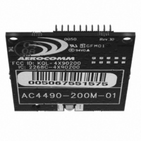
AC4490-200M-485 Laird Technologies, AC4490-200M-485 Datasheet - Page 14

AC4490-200M-485
Manufacturer Part Number
AC4490-200M-485
Description
TXRX 900MHZ 3.3-5.5V TTL 200MW
Manufacturer
Laird Technologies
Series
AeroCommr
Specifications of AC4490-200M-485
Frequency
902MHz ~ 928MHz
Data Rate - Maximum
115.2kbps
Modulation Or Protocol
FHSS, FSK
Applications
AMR, Fire & Security Alarms, Telemetry
Power - Output
5mW ~ 200mW
Sensitivity
-110dBm
Voltage - Supply
3.3V, 5V
Current - Transmitting
68mA
Data Interface
Connector, 2 x 10 Header
Antenna Connector
MMCX
Operating Temperature
-40°C ~ 85°C
Package / Case
Module
Wireless Frequency
900 MHz
Interface Type
20-pin mini connector
Modulation
FHSS, FSK
Security
1 byte System ID, DES
Operating Voltage
3.3 V to 5.5 V
Output Power
200 mW
Antenna
Integral and External Dipole
Lead Free Status / RoHS Status
Contains lead / RoHS non-compliant
Memory Size
-
Current - Receiving
-
Lead Free Status / Rohs Status
Lead free / RoHS Compliant
T
R F A R C H I T E C T U R E
The AC4490 utilizes a Server-Client network where all Clients synchronize their hopping to the Server. The Server
transmits a beacon at the beginning of every hop (20 ms). The Client transceivers listen for this beacon and upon
hearing it assert In_Range Low and synchronize their hopping with the Server.
Each network should consist of only one Server and there should never be two servers on the same RF Channel
number in the same coverage area as the interference between the two servers will severely hinder RF
communications. For those applications requiring collocated servers, we recommend using the Sync-to-Channel
feature explained in detail in the Sync-to-Channel Appendix.
M O D E S O F O P E R A T I O N
The AC4490 has three different operating modes; Receive, Transmit, & Command Mode. If the transceiver is not
communicating with another radio, it will be in Receive Mode actively listening for a beacon from the Server. If the
Client determines that the beacon is from a server operating on the same RF Channel and System ID, it will respond
by asserting In_Range Low. A transceiver will enter Transmit or Command mode when the OEM Host sends data over
the serial interface. The state of the CMD/Data pin (Pin 17) or the data contents determine which of the two modes will
be entered.
T r a n s m i t M o d e
All packets sent over the RF are either Addressed or Broadcast packets. Broadcast and Addressed delivery can be
controlled dynamically with the API Control byte and corresponding on-the-fly commands. To prohibit transceivers
from receiving broadcast packets, Unicast only can be enabled.
When sending an addressed packet, the RF packet is sent only to the receiver specified in destination address. To
increase the odds of successful delivery, Transmit retries are utilized. transparent to the OEM Host; the sending radio
will send the RF packet to the intended receiver. If the receiver receives the packet free of errors, it will return an RF
acknowledge within the same 20 ms hop. If a receive acknowledgement is not received, the radio will use a transmit
retry to resend the packet. The radio will continue sending the packet until either (1) an acknowledgement is received
or (2) all transmit retries have been used. The received packet will only be sent to the OEM Host if and when it is
received free of errors.
When sending a broadcast packet, the RF packet is broadcast to all eligible transceivers on the network. To increase
the odds of successful delivery, the radio uses Broadcast attempts. Transparent to the OEM Host, the sending radio
will send the RF packet to the intended receiver(s).
regardless of when the RF packet is actually received and without RF acknowledgements. If the packet is received on
the first attempt, the receiver will ignore the remaining broadcast attempts. The received packet will only be sent to
the OEM Host if and when it is received free of errors. Because of the inherent redundancy associated with Broadcast
Attempts, the overall latency may increase.
HEORY OF
A D D R E S S E D P A C K E T S
B R O A D C A S T P A C K E T S
O
PERATION
www.aerocomm.com
Unlike transmit retries, all broadcast attempts are used;
3


