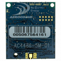
AC4486-5M Laird Technologies, AC4486-5M Datasheet - Page 5

AC4486-5M
Manufacturer Part Number
AC4486-5M
Description
TXRX 868MHZ 3V TTL 5MW RS232
Manufacturer
Laird Technologies
Series
AeroCommr
Specifications of AC4486-5M
Frequency
868MHz
Data Rate - Maximum
115.2kbps
Modulation Or Protocol
FSK
Applications
AMR, Gaming Devices, Inventory Tracking
Power - Output
5mW
Sensitivity
-100dBm
Voltage - Supply
3.3V
Current - Receiving
30mA
Current - Transmitting
40mA
Data Interface
Connector, 2 x 10 Header
Antenna Connector
MMCX
Operating Temperature
-40°C ~ 85°C
Package / Case
Module
Board Size
49 mm x 42 mm x 5 mm
Output Power
5 mW
Antenna
External MMCX Connector
Frequency Rf
869.65MHz
Transmit Power
5mW
Interface Type
Serial
Rohs Compliant
Yes
Lead Free Status / RoHS Status
Lead free / RoHS Compliant
Memory Size
-
Lead Free Status / Rohs Status
Lead free / RoHS Compliant
Available stocks
Company
Part Number
Manufacturer
Quantity
Price
Company:
Part Number:
AC4486-5M
Manufacturer:
Laird Technologies Wireless M2
Quantity:
135
5.
5.1
5.2
6.
7.
7.1
7.2
8.
8.1
8.2
8.3
8.4
8.5
Figures
Figure 1 – RSSI Voltage vs. Received Signal Strength................................................................................ 40
Figure 2 - AC4486 (with MMCX Connector) Mechanical .......................................................................... 49
Figure 3 - AC4486 (with Integral Splatch Antenna) Mechanical................................................................. 50
Tables
Table 1 – Pin Definitions................................................................................................................................ 9
Table 2 – Input Voltage Characteristics (AC4486-500) ............................................................................... 10
Table 3 – Input Voltage Characteristics (All Others) ................................................................................... 10
Table 4 – Output Voltage Characteristics (All) ............................................................................................ 10
Table 5 – Supported Serial Formats ............................................................................................................. 11
01/21/05
4.6.27
4.6.28
5.1.1
(pins 1 and 9 respectively).........................................................................................................................38
5.1.2
5.1.3
5.1.4
5.1.5
5.1.6
5.1.7
5.1.8
5.1.9
5.1.10
5.1.11
5.2.1
5.2.2
5.2.3
5.2.4
5.2.5
5.2.6
5.2.7
5.2.8
5.2.9
5.2.10
Interface Options .......................................................................................................................................48
THEORY OF OPERATION ..........................................................................................................38
H
S
DIMENSIONS .................................................................................................................................49
ORDERING INFORMATION.......................................................................................................51
P
D
AGENCY COMPLIANCY INFORMATION ..............................................................................52
A
OEM E
C
C
D
OFTWARE
RODUCT
OUNTRY
OUNTRY
ARDWARE INTERFACE
EVELOPER
PPROVED
ECLARATIONS OF CONFORMITY
EEPROM Byte Write .................................................................................................................37
Reset Command .........................................................................................................................37
GIn (Generic Inputs 0 and 1) (pins 4 and 14 respectively) and GOn (Generic Outputs 0 and 1)
TXD (Transmit Data) and RXD (Receive Data) (pins 2 and 3 respectively) .............................38
Hop Frame (pin 6).....................................................................................................................38
CTS Handshaking (pin 7) ..........................................................................................................39
RTS Handshaking (pin 8)...........................................................................................................39
9600 Baud (pin 12) ....................................................................................................................39
RSSI (pin 13)..............................................................................................................................39
UP_Reset (pin 15) .....................................................................................................................40
Command/Data (pin 17) ............................................................................................................40
AD In and DA Out (pins 18 and 19 respectively) ......................................................................41
In Range (pin 20).......................................................................................................................41
RF Architecture (Unicast/Broadcast)........................................................................................42
RF Mode ....................................................................................................................................42
Sub Hop Adjust ..........................................................................................................................43
Duplex Mode .............................................................................................................................43
Interface Timeout/RF Packet Size..............................................................................................43
Serial Interface Baud Rate.........................................................................................................44
Network Topology......................................................................................................................44
Auto Config................................................................................................................................45
One Beacon Mode .....................................................................................................................46
Max Power.................................................................................................................................47
QUIPMENT
P
R
N
A
P
ART
ESTRICTIONS
OTIFICATION
K
ARAMETERS
NTENNA
IT
N
P
UMBER
ART
L
ABELING
L
N
IST
......................................................................................................................38
UMBERS
...................................................................................................................42
T
...................................................................................................................53
...................................................................................................................53
.................................................................................................................52
REE
R
EQUIREMENTS
..........................................................................................................51
.......................................................................................................51
.......................................................................................................53
...................................................................................52
5


