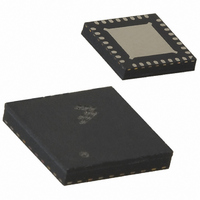
MC13202FC Freescale Semiconductor, MC13202FC Datasheet - Page 25

MC13202FC
Manufacturer Part Number
MC13202FC
Description
IC TXRX RF 2.4GHZ 32-QFN
Manufacturer
Freescale Semiconductor
Datasheet
1.MC13202FCR2.pdf
(30 pages)
Specifications of MC13202FC
Frequency
2.4GHz
Data Rate - Maximum
250kbps
Modulation Or Protocol
802.15.4
Applications
AMR, HID, HVAC, ISM
Power - Output
-27dBm ~ 3dBm
Sensitivity
-92dBm
Voltage - Supply
2 V ~ 3.4 V
Current - Receiving
37mA
Current - Transmitting
30mA
Data Interface
PCB, Surface Mount
Antenna Connector
PCB, Surface Mount
Operating Temperature
-40°C ~ 85°C
Package / Case
32-QFN
Operating Supply Voltage
2.7 V
Mounting Style
SMD/SMT
Minimum Operating Temperature
- 40 C
Operating Temperature (min)
-40C
Operating Temperature (max)
85C
Operating Temperature Classification
Industrial
Lead Free Status / RoHS Status
Lead free / RoHS Compliant
Memory Size
-
Lead Free Status / Rohs Status
Lead free / RoHS Compliant
9.2
Use of the RF interface pins and RF modes of operation are controlled through several bits of modem
Control_B Register 07.
highlighted.
The RF interface control bits include:
Freescale Semiconductor
•
•
•
RF_switch_mode (Bit 12) — This bit selects Dual Port Mode versus Single Port Mode:
— The default condition (Bit 12 = 0) is Dual Port Mode where the RF inputs are RFIN_M and
— When Bit = 1, the Single Port Mode is selected where RFIN_M (PAO_M) and RFIN_P
Ct_bias_en (Bit 14) — This bit is the enable for the CT_Bias output. When Bit 14 = 0 (default),
the CT_Bias is disabled and stays in a Hi-Z or tri-stated condition. When Bit 14 = 1, the CT_Bias
output is active and its state is controlled by the selected mode (Bit 12), ct_bias_inv, and operation
of the radio.
Ct_bias_inv (Bit 13) — This bit only affects the state of CT_Bias when Dual Port Mode is selected
and CT_bias is active. The CT_Bias changes state in Dual Port Mode based on the TX or RX state
of the radio. The ct_bias_inv bit causes the sense of the active state to change or invert based on
Bit 13’s setting. In this manner, the user can select the CT_Bias as a control signal for external
components and make the control signal active high or active low.
Controlling RF Modes of Operation
RFIN_P and the RF outputs are PAO_M and PAO_P, and operation is as described in
Section 9.1.2, “Dual Port
by Bit 13 and Bit 12.
(PAO_P) become bidirectional pins and operation is as described in
Operation”. The use of CT_Bias pin in Dual Port Mode in controlled by Bit 13 and Bit 12.
RESET
TYPE
BIT
r/w r/w r/w r/w r/w
Figure 15
15
0
14
0
13
0
Figure 15. Control_B Register 07 Model
shows the model for Register 07 with the RF interface control bits
12
0
Operation”. The use of CT_Bias pin in Dual Port Mode is controlled
MC13202 Technical Data, Rev. 1.5
11
1
10
Register 07
1
r/w
9
0
8
0
0x0C00
r/w r/w r/w
7
0
6
0
5
0
4
0
0x07
3
0
Section 9.1.1, “Single Port
2
0
r/w
1
0
r/w
0
0
25


