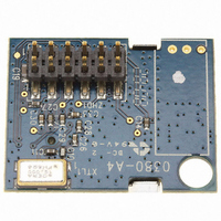
AWA24S Artaflex Inc, AWA24S Datasheet - Page 7

AWA24S
Manufacturer Part Number
AWA24S
Description
MODULE POWER AMPLIFIER
Manufacturer
Artaflex Inc
Series
WirelessUSB™r
Datasheet
1.AWA24S.pdf
(15 pages)
Specifications of AWA24S
Frequency
2.4GHz
Data Rate - Maximum
1Mbps
Modulation Or Protocol
DSSS, GFSK
Applications
Wireless Modules
Power - Output
-5dBm ~ 20dBm
Sensitivity
-93dBm
Voltage - Supply
2.5 V ~ 3.6 V
Current - Receiving
23mA
Current - Transmitting
195mA
Data Interface
Connector, 2 x 6 Header, 2mm Pitch
Antenna Connector
On-Board, Chip
Operating Temperature
0°C ~ 70°C
Package / Case
Module
Lead Free Status / RoHS Status
Lead free / RoHS Compliant
Memory Size
-
Other names
748-1003
Available stocks
Company
Part Number
Manufacturer
Quantity
Price
Company:
Part Number:
AWA24S
Manufacturer:
Artaflex Inc
Quantity:
135
The gain of the receiver may be controlled directly by clearing the AGC EN bit and writing to the Low Noise Amplifier (LNA) bit of
the RX_CFG_ADR register. When the LNA bit is cleared, the receiver gain is reduced by approximately 20 dB, allowing accurate
reception of very strong received signals (for example when operating a receiver very close to the transmitter). Approximately 30
dB of receiver attenuation can be added by setting the Attenuation (ATT) bit; this allows data reception to be limited to devices at
very short ranges. Disabling AGC and enabling LNA is recommended for static long range application. When the module is in
receive mode the RSSI_ADR register returns the relative signal strength of the on-channel signal power.
When receiving, the module will automatically measure and store the relative strength of the signal being received as a 5- bit value.
An RSSI reading is taken automatically when the SOP is detected. In addition, a new RSSI reading is taken every time the
previous reading is read from the RSSI_ADR register, allowing the background RF energy level on any given channel to be easily
measured when RSSI is read when no signal is being received. A new reading can occur as fast as once every 12 µs.
The RF Amplifier used in this module is a GaAs MMIC. This device realizes high efficiency, high gain and high output power,
housed in a 6-pin plastic package TSON (Thin small Out-line Non Leaded). It has a very low shut down current (5uA) as well
as a very high power efficiency (up to 60%), these features enables the module to work longer in a power sensitive
applications.
The Tx and Rx operations of the additional Amplifier circuitry on this module is controlled by using Pin 11(TXPA), Pin 12
(RXPA) and Pin 10 (PACTL) on the 12 Pin Header Interface.
For a typical Full power Amplifier application, TXPA and PACTL pins can be tied together as they need the same logic
levels for RX/TX control. The RF power can be set by setting different power levels in the TX_CFG_ADR register. The RF
specs on page 11 of this data sheet describes the TX power levels available with this software control. PACTL will require a
strong current drive as it can sink up to 10mA of current when biased at 3.3V
Amplifier RF Power can also be changed by controlling the voltage level at PACTL (0.5V-3.3V) independently. Biasing 3.3V
at “PACTL” will set up the power to the maximum. A “0V” at PACTL will bring only the Amplifier stage into a shutdown mode.
. All three pins (Pin 10,11,12) are required to control the amplifier in a proper manner. PACTL should always be set to 0V in
a receive mode.
Artaflex Inc.
Markham, Ontario, Canada
L3R8T9
905-479-0148
215 Konrad Crescent
7
8
Table 2 – Radio Mode
Low Noise Amplifier (LNA) and Received Signal Strength Indication (RSSI)
RF Amplifier Stage
Radio Mode
Transmit
Receive
Low (0V)
High (3.3V)
TXPA (Pin 11)
2.4GHz Radio Module with Integrated Power Amplifier
RXPA (Pin 12)
High (3.3V)
Low (0v)
Page 7 of 15
*PACTL (Pin 10)
0V
0.5V – 3.3V
http://www.artaflexmodules.com
Revised October 6, 2008
DSAWA24S Rev 2v6
Data Sheet
AWA24S


