MRF24WB0MB/RM Microchip Technology, MRF24WB0MB/RM Datasheet - Page 7
MRF24WB0MB/RM
Manufacturer Part Number
MRF24WB0MB/RM
Description
TXRX RF 2.4GHZ EXT ANT 802.11B
Manufacturer
Microchip Technology
Specifications of MRF24WB0MB/RM
Frequency
2.4GHz
Data Rate - Maximum
1Mbps
Modulation Or Protocol
802.11 b
Applications
ISM
Power - Output
10dBm
Sensitivity
-91dBm
Voltage - Supply
2.7 V ~ 3.6 V
Current - Receiving
85mA
Current - Transmitting
154mA
Data Interface
PCB, Surface Mount
Antenna Connector
U.FL
Operating Temperature
0°C ~ 70°C
Package / Case
Module
Wireless Frequency
2.4 GHz
Interface Type
SPI, JTAG
Board Size
21 mm x 31 mm
Modulation
DSSS
Security
WEP, WPA-PSK, WPA-2-PSK
Operating Voltage
2.7 V to 3.6 V
Antenna
U.FL
Operating Temperature Range
0 C to + 70 C
Module Interface
SPI, 4-Wire
Data Rate Max
2Mbps
Modulation Type
DSSS
Supply Current
154mA
Supply Voltage Range
2.7V To 3.6V
Frequency Range
2.4GHz
Leaded Process Compatible
Yes
Peak Reflow Compatible (260 C)
Yes
Rohs Compliant
No
For Use With/related Products
PIC18, PIC24, dsPIC33, PIC32
Lead Free Status / RoHS Status
Lead free / RoHS Compliant
Memory Size
-
Lead Free Status / Rohs Status
Lead free / RoHS Compliant
Available stocks
Company
Part Number
Manufacturer
Quantity
Price
Company:

Part Number:
MRF24WB0MB/RM
Manufacturer:
RENESAS
Quantity:
4 492


1.0
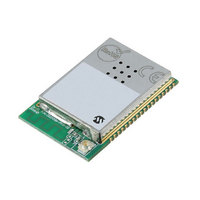
The MRF24WB0MA and MRF24WB0MB are low-
power, 2.4 GHz, IEEE Std. 802.11-compliant, surface
mount modules with all associated RF components –
crystal oscillator, bypass and bias passives with inte-
grated MAC, baseband, RF and power amplifier, and
built-in hardware support for AES, and TKIP (WEP,
WPA, WPA2 security). The integrated module design
frees the designer from RF and antenna design tasks
and regulatory compliance testing, ultimately providing
quicker time to market.
The MRF24WB0MA module is approved for use with
the integrated PCB meander antenna.
The MRF24WB0MB comes with an ultra miniature
coaxial connector (U.FL) and is approved for use with
a list of pre-certified antennas. See Section 2.8
“External Antenna”, for specific recommendations.
The MRF24WB0MA/MRF24WB0MB modules are
designed to be used with Microchip’s TCP/IP software
stack. The software stack has an integrated driver that
implements the API that is used in the modules for
command and control, and for management and data
packet traffic.
The Microchip TCP/IP software stack is available in the
free Microchip Application Libraries download (includ-
ing example applications and source code) from the
Microchip web site, http://www.microchip.com/wireless
The combination of the module and a PIC running the
TCP/IP stack results in support for IEEE Standard
802.11 and IP services. This allows, for example, the
immediate implementation of a wireless web server.
FIGURE 1-1:
2010 Microchip Technology Inc.
(MRF24WB0MA
DEVICES OVERVIEW
Antenna
PCB
MRF24WB0MA
MRF24WB0MA/MRF24WB0MB BLOCK DIAGRAM
)
2. 4 GHz IEEE Std. 802.11b RF Transceiver Module
Matching
FLASH
Circuitry
MRF24WB0MA/MRF24WB0MB
Preliminary
Transceiver
AES TKIP
Accelerator
Encryption
2.4 GHz
Amplifier
Power
,
The MRF24WB0MA/MRF24WB0MB modules have
received regulatory approvals for modular devices in
the United States (FCC), Canada (IC), and Europe
(ETSI). The modular approval removes the need for
expensive RF and antenna design, and allows the end
user to place the modules inside a finished product and
not require regulatory testing for an intentional radiator
(RF transmitter). They also have Radio Type Approval
Certification for Japan. See Section 3.0 “Regulatory
Approval”, for the specific requirements that should be
adhered to by the integrator.
1.1
The block diagram in Figure 1-1 represents a
MRF24WB0MA/MRF24WB0MB module. It interfaces
to a Microchip PIC18, PIC24, dsPIC33, or PIC32 micro-
controllers via a four-wire serial slave SPI interface –
interrupt, hibernate, Reset, power and ground signals.
The module runs on a single supply voltage of nomi-
nally 3.3v. It also supports optional JTAG and serial
debug for testability. The debug port operates at 3.3v
and requires a level shifter for operation with RS-232
devices. Figure 1-2 shows a simplified example con-
nection between a Microchip PIC MCU and the mod-
ule. Table 1-1 lists the pin descriptions.
Data
MRF24WB0MB are through the SPI interface that is
detailed in Section 2.0 “Circuit Description”. The
Microchip PIC microcontroller communicates with the
module via a command API from within the Microchip
TCP/IP stack. The command API is detailed in the
Microchip TCP/IP Stack online help that is included in
the free Microchip Application Libraries download.
communications
Interface
Interface Description
ROM
RAM
with
SPI
the
DS70632A-page 7
MRF24WB0MA/
Digital I/O
Interrupt
Debug
Reset
Hibernate
Power
JTAG
Related parts for MRF24WB0MB/RM
Image
Part Number
Description
Manufacturer
Datasheet
Request
R

Part Number:
Description:
Manufacturer:
Microchip Technology Inc.
Datasheet:
Part Number:
Description:
Manufacturer:
Microchip Technology Inc.
Datasheet:
Part Number:
Description:
Manufacturer:
Microchip Technology Inc.
Datasheet:
Part Number:
Description:
Manufacturer:
Microchip Technology Inc.
Datasheet:
Part Number:
Description:
Manufacturer:
Microchip Technology Inc.
Datasheet:
Part Number:
Description:
Manufacturer:
Microchip Technology Inc.
Datasheet:
Part Number:
Description:
Manufacturer:
Microchip Technology Inc.
Datasheet:
Part Number:
Description:
Manufacturer:
Microchip Technology Inc.
Datasheet: