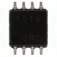
NJG1516R-TE1 NJR, NJG1516R-TE1 Datasheet - Page 3

NJG1516R-TE1
Manufacturer Part Number
NJG1516R-TE1
Description
IC MMIC SWITCH SPDT 8-VSP
Manufacturer
NJR
Series
-r
Datasheet
1.NJG1516R-TE1.pdf
(14 pages)
Specifications of NJG1516R-TE1
Rf Type
GSM
Frequency
1MHz ~ 3GHz
Features
SPDT
Package / Case
8-VSP
Lead Free Status / RoHS Status
Contains lead / RoHS non-compliant
Other names
NJG1516R-TE1TR
*2: The input IP3 is defined as following equation.
ELECTRICAL CHARACTERISTICS (Cellular Band)
Frequency range
Control voltage (HIGH)
Insertion Loss 5
Isolation 3
Pout at 0.2dB Gain
Input 3rd Order
Input 3rd Order
Second Harmonics
Third Harmonics
VSWR 2 (PC, P1, P2)
(PC-P1, PC-P2)
Compression point 2
Intercept Point 1
Intercept Point 2
PARAMETERS
IIP3 = (3 x Pout – IM3) / 2 + LOSS
SYMBOL
VSWR2
LOSS5
P
IIP3(1)
IIP3(2)
V
ISL3
-0.2dB
CTL(H)
2fo
3fo
f
in
2
P
P
P
f=900+901MHz, P
V
f=900+901MHz, P
V
f=900MHz, P
2nd Harmonics of Input Signal
= -83dBc
f=900MHz, P
3rd Harmonics of Input Signal
=-100dBc
ON State
in
in
in
CTL(H)
CTL(H)
=25dBm
=25dBm
=25dBm
=3V, V
=2.7V, V
CONDITIONS
in
in
CTL(L)
=25dBm
=25dBm
CTL(L)
(V
=0V
CTL (L)
in
in
=25dBm,
=25dBm
=0V
*2
=0V, V
*2
CTL (H)
33.5
MIN
800
=2.7V, Z
2.7
26
-
-
-
-
-
TYP
1.15
0.4
-80
-70
27
35
62
60
-
-
s
=Z
NJG1516R
l
=50Ω, T
1000
MAX UNITS
1.25
0.5
9
-
-
-
-
-
-
a
=25°C)
MHz
dBm
dBm
dBm
dBc
dBc
dB
dB
V
- 3 -


