ADG919BRMZ Analog Devices Inc, ADG919BRMZ Datasheet
ADG919BRMZ
Specifications of ADG919BRMZ
Available stocks


Related parts for ADG919BRMZ


ADG919BRMZ Summary of contents
Page 1
FEATURES Wideband switch: − GHz Absorptive/reflective switches High off isolation ( GHz) Low insertion loss (0 GHz) Single 1. 2.75 V power supply CMOS/LVTTL control logic 8-lead MSOP and tiny ...
Page 2
ADG918/ADG919 TABLE OF CONTENTS ADG918/ADG919–Specifications ................................................. 3 Absolute Maximum Ratings............................................................ 4 ESD Caution.................................................................................. 4 Pin Configuration and Function Descriptions............................. 5 Terminology ...................................................................................... 6 Typical Performance Characteristics ............................................. 7 Test Circuits..................................................................................... 10 Applications..................................................................................... 12 REVISION HISTORY 9/04—Changed from Rev ...
Page 3
SPECIFICATIONS Table 1. 2.75 V, GND = 0 V, input power = 0 dBm, all specifications T DD Parameter AC ELECTRICAL CHARACTERISTICS Operating Frequency Frequency 4 Input Power Insertion Loss Isolation—RFC ...
Page 4
ADG918/ADG919 ABSOLUTE MAXIMUM RATINGS Table 25°C, unless otherwise noted.) A Parameter V to GND DD Inputs to GND Continuous Current Input Power Operating Temperature Range Industrial (B Version) Storage Temperature Range Junction Temperature MSOP Package θ Thermal ...
Page 5
PIN CONFIGURATION AND FUNCTION DESCRIPTIONS Table 3. Truth Table CTRL Signal Path 0 RF2 to RFC 1 RF1 to RFC Table 4. Pin Function Descriptions Pin No. Mnemonic Function 1 V Power Supply Input. These parts can be operated from ...
Page 6
ADG918/ADG919 TERMINOLOGY Table 5. Terminology Parameter Description V Most positive power supply potential DD I Positive supply current DD GND Ground (0 V) reference CTRL Logic control input V Maximum input voltage for Logic 0 INL V Minimum input voltage ...
Page 7
TYPICAL PERFORMANCE CHARACTERISTICS –0.2 –0.4 –0 2.25V –1.0 –1.2 –1.4 –1 –1.8 –2.0 –2.2 –2.4 –2.6 –2.8 –3 25°C A –3.2 10k 100k 1M 10M 100M FREQUENCY (Hz) Figure ...
Page 8
ADG918/ADG919 –10 – 2.5V DD –30 –30 –40 –40 S12 (+85°C) –50 –50 –60 –60 S12 (+25°C) –70 –70 S12 (–40°C) –80 –80 –90 –90 S21 (–40°C, +25°C, +85°C) –100 –100 10k 100k 1M 10M FREQUENCY (Hz) Figure ...
Page 9
25° 250 500 750 1000 1250 FREQUENCY (MHz) Figure 17. P vs. Frequency -1dB 1500 Rev Page 9 of ...
Page 10
ADG918/ADG919 * TEST CIRCUITS V DD 0.1µ RFx OUT RFC R V CTRL 50Ω CTRL V OUT GND Figure 18. Switch Timing 0.1µ RFC RFx OUT V CTRL ...
Page 11
V DD 0.1µF V ADG919 DD RF1 RFC SPECTRUM ANALYZER RF2 CTRL V CTRL GND Figure 24 Similar setups for ADG918 50Ω RF SOURCE SPECTRUM ANALYZER COMBINER RF SOURCE Rev Page ADG918/ADG919 ...
Page 12
ADG918/ADG919 APPLICATIONS The ADG918/ADG919 are ideal solutions for low power, high frequency applications. The low insertion loss, high isolation between ports, low distortion, and low current consumption of these parts make them excellent solutions for many high frequency switching applications. ...
Page 13
ADG9XX EVALUATION BOARD The ADG9xx evaluation board allows designers to evaluate the high performance wideband switches with a minimum of effort. To prove that these devices meet the user’s requirements, the user only requires a power supply and a network ...
Page 14
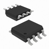
ADG918/ADG919 OUTLINE DIMENSIONS 3.00 BSC 8 5 4.90 3.00 BSC BSC 4 PIN 1 0.65 BSC 1.10 MAX 0.15 0.00 0.38 0.23 0.22 0.08 COPLANARITY SEATING 0.10 PLANE COMPLIANT TO JEDEC STANDARDS MO-187AA Figure 30. 8-Lead Mini Small Outline Package ...
Page 15
NOTES Rev Page ADG918/ADG919 ...
Page 16
ADG918/ADG919 NOTES © 2004 Analog Devices, Inc. All rights reserved. Trademarks and registered trademarks are the property of their respective owners. C03335–0–9/04(A) Rev Page ...