BMI-S-207-F Laird Technologies, BMI-S-207-F Datasheet

BOARD SHIELD 1.747X1.747" FRAME

BMI-S-207-F

Manufacturer Part Number
BMI-S-207-F
Description
BOARD SHIELD 1.747X1.747" FRAME
Manufacturer
Laird Technologies
Type
Framer
Datasheets

Specifications of BMI-S-207-F

Length - Overall
1.747" (44.37mm)
Width - Overall
1.747" (44.37mm)
Height - Overall
0.384" (9.75mm)
Mounting Type
Solder
Lead Free Status / RoHS Status
Lead free / RoHS Compliant
Other names
903-1056-2
BMI-S-207-F
Innovative Technology
global
USA: +1.866.928.8181
Europe: +49.0.8031.2460.0
Asia: +86.755.2714.1166
www.lairdtech.com
for a Connected World
solutions:
local
support
TM
Rigid CoRneR BoaRd-LeveL shieLd
The rigid corner board-level shield incorporates a corner design that optimizes component
rigidity for increased part and printed circuit board (PCB) firmness. As PCB designers are
increasingly using thinner substrates, a rigid frame reinforces the assembly, thereby improving
overall ruggedness and performance. The shield has improved solder joint reliability and resistance
to solder joint fracture, especially in drop testing performance with thin PCBs. Several standard
Laird Technologies EMI style parts including single-piece, two-piece, and multi-compartmental
board-level shields use this new rigid corner design, along with availability in custom sizes as well.
The rigid corner shield is stronger and more robust than traditional formed shields, which results
in coplanarity improvement of the solder castellations. The shield can tolerate more deflection
(i.e., more handling) without plastic deformation. Elimination of drawn flange reduces the space
needed on the PCB for shielding trace width by potentially ~0.3 mm, allowing for the shield to
be more closely placed on the PCB. Elimination of draft allows for more undershield space and
improved component clearance.
The partially drawn corner is located near the top portion the shield, resulting in improved
torsional rigidity with no drawn lip and no draft. For parts over 2 mm, the corner is both drawn
and formed with an interlocking multi-radius corner, which provides superior EMI shielding
effectiveness. The interlocking corner can be meshed and closed in during the forming and
drawing process for additional improved rigidity for parts taller than 2 mm. For parts under 2 mm,
the entire corner is drawn without an interlocking corner.
BeneFits
• Shield can tolerate more deflection (handling)
• Shield provides increased stiffness to the PCB
• Tooling costs are not impacted
• Elimination of draft allows for more undershield
FeatuRes
• Corner openings are reduced,
improving shielding performance
• Partially drawn corner located near the top
portion of the corner combined with 90°
straight forming of wall sections for improved
torsional rigidity.
• U.S. Patent No. 7,488,902
without plastic deformation
space and component clearance
MaRkets
• Computing
• Telecommunications
• Data Transfer and Information Technology
• Automotive
• Consumer Electronics
• Aerospace / Defense
• Medical
• Portability
• Industrial & Instrumentation
• Public Utilities
Board-Level Shield
Rigid Corner

Related parts for BMI-S-207-F

BMI-S-207-F Summary of contents

Page 1

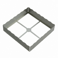
Innovative Technology for a Connected World Rigid CoRneR BoaRd-LeveL shieLd The rigid corner board-level shield incorporates a corner design that optimizes component rigidity for increased part and printed circuit board (PCB) firmness. As PCB designers are increasingly using thinner substrates, a rigid frame reinforces the assembly, thereby improving overall ruggedness and performance. The shield has improved solder joint reliability and resistance to solder joint fracture, especially in drop testing performance with thin PCBs. Several standard Laird Technologies EMI style parts including single-piece, two-piece, and multi-compartmental board-level shields use this new rigid corner design, along with availability in custom sizes as well. The rigid corner shield is stronger and more robust than traditional formed shields, which results in coplanarity improvement of the solder castellations. The shield can tolerate more deflection (i.e., more handling) without plastic deformation. Elimination of drawn flange reduces the space needed on the PCB for shielding trace width by potentially ~0.3 mm, allowing for the shield to be more closely placed on the PCB. Elimination of draft allows for more undershield space and improved component clearance. The partially drawn corner is located near the top portion the shield, resulting in improved torsional rigidity with no drawn lip and no draft. For parts over 2 mm, the corner is both drawn and formed with an interlocking multi-radius corner, which provides superior EMI shielding effectiveness. The interlocking corner can be meshed and closed in during the forming and drawing process for additional improved rigidity for parts taller than 2 mm. For parts under 2 mm, the entire corner is drawn without an interlocking corner. FeatuRes • Corner openings are reduced, improving shielding performance • Partially drawn corner located near the top portion of the corner combined with 90° straight forming of wall sections for improved torsional rigidity. • U.S. Patent No. 7,488,902 ...

Page 2

... Technologies materials or products for any specific or general uses. laird Technologies shall not be liable for incidental or consequential damages of any kind. All laird Technologies products are sold pursuant to the laird Technologies’ Terms and Conditions of sale in effect from time to time, a copy of which will be furnished upon request. © Copyright 2009 laird Technologies, Inc. All Rights Reserved ...

Related keywords