MICRF011BN Micrel Inc, MICRF011BN Datasheet - Page 8
MICRF011BN
Manufacturer Part Number
MICRF011BN
Description
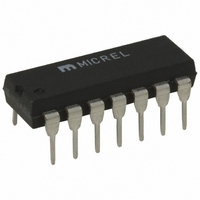
IC RCVR/DATA DEMOD RF/IF 14DIP
Manufacturer
Micrel Inc
Datasheet
1.MICRF011YM.pdf
(11 pages)
Specifications of MICRF011BN
Frequency
300MHz ~ 440MHz
Sensitivity
-103dBm
Data Rate - Maximum
10 kbps
Modulation Or Protocol
OOK
Applications
Garage Openers
Current - Receiving
2.4mA
Data Interface
PCB, Surface Mount
Antenna Connector
PCB, Surface Mount
Features
Automatic Tuning
Voltage - Supply
4.75 V ~ 5.5 V
Operating Temperature
-40°C ~ 85°C
Package / Case
14-DIP (0.300", 7.62mm)
Operating Band Frequency
300 to 440MHz
Operating Temperature (min)
-40C
Operating Temperature (max)
85C
Operating Temperature Classification
Industrial
Operating Supply Voltage (min)
4.75V
Operating Supply Voltage (typ)
5V
Operating Supply Voltage (max)
5.5V
Lead Free Status / RoHS Status
Contains lead / RoHS non-compliant
Memory Size
-
Lead Free Status / Rohs Status
Not Compliant


MICRF011
[By adding resistance from the CAGC pin to VDDBB or
VSSBB in parallel with the CAGC capacitor, the ratio of
decay-to-attack time-constant may be varied, although the
value of such adjustments must be studied on a per-
application basis.
adequate for the vast majority of applications.]
“Application Note 22”.
To maximize system range, it is important to keep the AGC
control voltage ripple low, preferably under 10mVpp once
the control voltage has attained its quiescent value. For this
reason capacitor values
Reference Oscillator (REFOSC) and External Timing
Element
All timing and tuning operations on the MICRF011 are
derived from the REFOSC function.
single-pin Colpitts-type oscillator. The user may handle this
pin in one of three possible ways:
The third approach is attractive for further lowering system
cost if an accurate reference signal exists elsewhere in the
system (e.g., a reference clock from a crystal or ceramic
resonator-based microprocessor).
signal should be AC-coupled, and resistively-divided down
(or otherwise limited) to approximately 0.5Vpp. The specific
reference frequency required is related to the system
transmit frequency, and the operating mode of the device as
set by the SWEN control pin. See “Application Note 22,
MICRF001 Theory of Operation” for a discussion of
frequency selection and accuracy requirements.
MICRF011 Frequency and Capacitor Selection
Selection of the REFOSC frequency ft, Slicing Level (CTH)
capacitor, and AGC capacitor are briefly summarized in this
section.
details.
1. Selecting REFOSC Frequency ft (FIXED Mode)
As with any superheterodyne receiver, the difference
between the (internal) Local Oscillator (LO) frequency flo
and the incoming Transmit frequency ftx must ideally equal
the IF Center frequency.
compute the appropriate flo for a given ftx:
flo = ftx
where ftx and flo are in MHz. Note that two values of flo
exist for any given ftx, distinguished as “high-side mixing”
and “low-side mixing”, and there is generally no preference
of one over the other.
After choosing one of the two acceptable values of flo, use
equation (2) to compute the REFOSC frequency ft:
ft = flo / 64.5.
December 1998b
(1) connect a ceramic resonator, or
(2) connect a crystal, or
(3) drive this pin with an external timing signal.
1.064 * (ftx / 390)
Please see Application Note 22 for complete
Generally the design value of 10:1 is
0.47uF are recommended.
Equation (1) may be used to
An externally applied
This function is a
(2)
(1)
QwikRadio
See
88
Here ft is in MHz. Connect a crystal of frequency ft to the
REFOSC pin of the MICRF011. 4 decimal-place accuracy
on the frequency is generally adequate. The following table
identifies ft for some common Transmit frequencies when
the MICRF011 is operated in FIXED mode.
2.
Selection of REFOSC frequency ft in SWP mode is much
simpler than in FIXED mode, due to the LO sweeping
process. Further, accuracy requirements of the frequency
reference component are significantly relaxed.
In SWP mode, ft is given by equation (3):
ft = ftx / 64.25.
Connect a ceramic resonator of frequency ft to the REFOSC
pin of the MICRF011. 2-decimal place accuracy is generally
adequate. (A crystal may also be used if desired, but may
be necessary to reduce the Rx frequency ambiguity if the Tx
frequency ambiguity is excessive. See Application Note 22
for further details.)
3. Selecting Capacitor CTH
First step in the process is selection of a Data Slicing Level
timeconstant.
system issues, like system decode response time and data
code structure (e.g., existence of data preamble, etc.). This
issue is too broad to discuss here, and the interested reader
should consult the Application Note 22.
Source impedance of the CTH pin is given by equation (4),
where ft is in MHz:
Rsc = 118k
Assuming that a Slicing Level Timeconstant TC has been
established, capacitor CTH may be computed using
equation (5):
CTH = TC / Rsc.
Transmit Freq. ftx (MHz)
tm
Selecting REFOSC Frequency ft (SWP Mode)
433.92
* (4.90 / ft).
315
418
This selection is strongly dependent on
REFOSC Freq. ft (MHz)
4.8970
6.4983
6.7458
MICRF011
Micrel
(4)
(5)
(3)
Related parts for MICRF011BN
Image
Part Number
Description
Manufacturer
Datasheet
Request
R


Part Number:
Description:
MICR CTL LP 1K 4MHZ OTP ET 18DIP
Manufacturer:
Microchip Technology
Datasheet:

Part Number:
Description:
Manufacturer:
Micrel Inc
Datasheet:
Part Number:
Description:
Manufacturer:
Micrel Inc
Datasheet:
Part Number:
Description:
Manufacturer:
Micrel Inc
Datasheet:
Part Number:
Description:
Manufacturer:
Micrel Inc
Datasheet:
Part Number:
Description:
Manufacturer:
Micrel Inc
Datasheet:
Part Number:
Description:
Manufacturer:
Micrel Inc
Datasheet:
Part Number:
Description:
Manufacturer:
Micrel Inc
Datasheet:
Part Number:
Description:
Manufacturer:
Micrel Inc
Datasheet:
Part Number:
Description:
Manufacturer:
Micrel Inc
Datasheet:
Part Number:
Description:
Manufacturer:
Micrel Inc
Datasheet:
Part Number:
Description:
Manufacturer:
Micrel Inc
Datasheet:
Part Number:
Description:
Manufacturer:
Micrel Inc
Datasheet: