AA003041-G Navman Wireless, AA003041-G Datasheet - Page 12
AA003041-G
Manufacturer Part Number
AA003041-G
Description
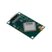
MODULE JUPITER 31 GPS W/R/A OSX
Manufacturer
Navman Wireless
Specifications of AA003041-G
Frequency
1.575GHz
Sensitivity
-159dBm
Modulation Or Protocol
GPS
Applications
GPS
Data Interface
Connector, 2 x 10 Header, 2 mm Pitch
Antenna Connector
OSX
Voltage - Supply
3.3V
Operating Temperature
-40°C ~ 85°C
Package / Case
Module
Lead Free Status / RoHS Status
Lead free / RoHS Compliant
Features
-
Memory Size
-
Data Rate - Maximum
-
Current - Receiving
-
Other names
943-1007


5.2 External antenna voltage
The Jupiter 31 provides DC power to the external active antenna through the antenna power
input pad (VANT). The DC supply in the coax cable is vulnerable to over current if a fault occurs
in the antenna or if the antenna cable gets damaged.
Typical values for the external antenna are shown in Table 5-1.
5.3 External I/O connector
The OEM communications interface is a dual row, straight 2 x 10-pin field connector header (J1).
The pins are spaced on 2.0 mm centres and the pin lengths are 7.0 mm off the board surface
with 1.3 mm at the base for plastic form. Figure 5-1 shows the 20-pin I/O connector. The mating
female connector is an IDC receptacle.
LA010811B © 2008 Navman Wireless OEM Solutions. All rights reserved. Proprietary information and specifications subject to change without notice.
5.3.1 I/O connector signals
Table 5-2 shows the name and function of each connector pin:. A further description of each
pin follows these tables.
J1
10
12
13
14
15
16
18
19
20
11
17
1
2
3
4
5
6
7
8
9
voltage (typ)
voltage max
antenna current limit
WAKE-UP
GPIO 14
GPIO 15
PWRIN
PWRIN
RESET
GPIO 1
VBATT
Name
BOOT
VANT
GND
RXA
GND
GND
GND
GND
TXA
RXB
TXB
PPS
Table 5-2: J1 connector pin functions
Table 5-1: External antenna voltages
Parameter
Type
I/O
I/O
I/O
O
O
O
P
P
P
P
P
P
P
P
P
I
I
I
I
I
external power supply for active antenna
primary VDC power input
backup battery input
primary VDC power input
master reset (active low)
reserved - no connect
reserved - no connect
serial boot (active low; can be held high or open
circuit for normal operation)
reserved - no connect
ground
CMOS level asynchronous output for UART A
CMOS level asynchronous input for UART A
ground
CMOS level asynchronous output for UART B
CMOS level asynchronous input for UART B
ground
ground
ground
pulse per second output 1uS wide
PTF wake-up, active on positive-going edge
Description
12 VDC
3 VDC
50 mA
J31
12
Related parts for AA003041-G
Image
Part Number
Description
Manufacturer
Datasheet
Request
R

Part Number:
Description:
ANTENNA GPS ACTIVE 5M CABLE
Manufacturer:
Navman Wireless
Datasheet:

Part Number:
Description:
DEV KIT FOR JUPITER 32XLP
Manufacturer:
Navman Wireless
Datasheet:

Part Number:
Description:
DEV KIT FOR JUPITER 30XLP
Manufacturer:
Navman Wireless
Datasheet:

Part Number:
Description:
DEV KIT FOR JUPITER 3 AND J3-30
Manufacturer:
Navman Wireless
Datasheet:

Part Number:
Description:
TERMINAL MDT-860 MOBILE DATA
Manufacturer:
Navman Wireless
Datasheet:


Part Number:
Description:
MODULE GPS RECEIVER JUPITER 3
Manufacturer:
Navman Wireless
Datasheet:

Part Number:
Description:
MODULE GPS JUPITER 30XLP 20CH
Manufacturer:
Navman Wireless
Datasheet:

Part Number:
Description:
MODULE GPS JUPITER 32XLP 20CH
Manufacturer:
Navman Wireless
Datasheet:

Part Number:
Description:
MODULE GPS RECEIVER JUPITER 3-30
Manufacturer:
Navman Wireless
Datasheet:

Part Number:
Description:
MODULE GPS RECEIVER JUPITER 2
Manufacturer:
Navman Wireless
Datasheet:

Part Number:
Description:
DEV KIT FOR MDT860
Manufacturer:
Navman Wireless
Datasheet:

Part Number:
Description:
EVAL KIT GPS JUPITER 2
Manufacturer:
Navman Wireless
Datasheet: