J3,3000,00,3.5 Navman Wireless, J3,3000,00,3.5 Datasheet - Page 10
J3,3000,00,3.5
Manufacturer Part Number
J3,3000,00,3.5
Description
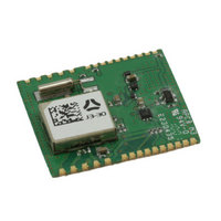
MODULE GPS RECEIVER JUPITER 3-30
Manufacturer
Navman Wireless
Datasheet
1.J330DK003.5.pdf
(17 pages)
Specifications of J3,3000,00,3.5
Frequency
1.575GHz
Sensitivity
-159dBm
Data Rate - Maximum
38.4kbps
Modulation Or Protocol
GPS
Applications
GPS
Data Interface
PCB, Surface Mount
Memory Size
4Mb Flash
Antenna Connector
PCB, Surface Mount
Voltage - Supply
3 V ~ 3.6 V
Operating Temperature
-40°C ~ 85°C
Package / Case
Module
Lead Free Status / RoHS Status
Lead free / RoHS Compliant
Features
-
Current - Receiving
-
Other names
943-1011-2


Jupiter 3-30
5.1.6 Antenna gain
The receiver will operate with a passive antenna with unity gain. However, GPS performance will be optimum when
an active antenna is used. The gain of this antenna at the input of the module should ideally be 16 dB.
For recommendations on antenna use and testing see the Jupiter 3-30 Integrator’s manual (LA000577).
5.1.7 Burnout protection
The receiver accepts without risk of damage a signal of +10 dBm from 0 to 2 GHz carrier frequency, except in band
1560 to 1590 MHz where the maximum level is –10 dBm.
5.1.8 Jamming performance
The typical jamming performance of the receiver based upon a 3 dB degradation in C/N0 performance is shown in
Table 5-2. This is with reference to the external antenna.
5.1.9 Flash upgradability
The firmware programmed in the Flash memory may be upgraded via the serial port. The user can control this
by driving the Serial BOOT (pad 3) high at startup, then downloading the code from a PC with suitable software
(e.g. SiRFFlash). In normal operation this pad should be left floating for minimal current drain. It is recommended
that in the user’s application, the BOOT pad is connected to a test pad for use in future software upgrades.
5.1.10 Reset input
This active low input (pad 22) allows the user to restart the software from an external signal. In normal operation this
pad should be left floating or activated by an open drain driver. Active pull-up is not recommended.
Navman Wireless OEM Solutions • 27171 Burbank -Suite 200; Foothill Ranch, CA 92610-2501
TEL: +(949) 461-7150 • FAX: +(949) 461-7860 • www.navmanwirelessoem.com
|
Datasheet
Table 5-2: Typical jamming performance
frequencymHz
1575.42
1550
1555
1560
1565
1570
1574
1576
1580
1585
1590
1595
1600
Jammingsignal
powerdBm
-22
-25
-38
-45
-65
-85
-90
-85
-77
-70
-55
-37
-23
8
Related parts for J3,3000,00,3.5
Image
Part Number
Description
Manufacturer
Datasheet
Request
R

Part Number:
Description:
ANTENNA GPS ACTIVE 5M CABLE
Manufacturer:
Navman Wireless
Datasheet:

Part Number:
Description:
DEV KIT FOR JUPITER 32XLP
Manufacturer:
Navman Wireless
Datasheet:

Part Number:
Description:
DEV KIT FOR JUPITER 30XLP
Manufacturer:
Navman Wireless
Datasheet:

Part Number:
Description:
DEV KIT FOR JUPITER 3 AND J3-30
Manufacturer:
Navman Wireless
Datasheet:

Part Number:
Description:
TERMINAL MDT-860 MOBILE DATA
Manufacturer:
Navman Wireless
Datasheet:


Part Number:
Description:
MODULE GPS RECEIVER JUPITER 3
Manufacturer:
Navman Wireless
Datasheet:

Part Number:
Description:
MODULE GPS JUPITER 30XLP 20CH
Manufacturer:
Navman Wireless
Datasheet:

Part Number:
Description:
MODULE GPS JUPITER 32XLP 20CH
Manufacturer:
Navman Wireless
Datasheet:

Part Number:
Description:
MODULE JUPITER 31 GPS W/R/A OSX
Manufacturer:
Navman Wireless
Datasheet:

Part Number:
Description:
MODULE GPS RECEIVER JUPITER 2
Manufacturer:
Navman Wireless
Datasheet:

Part Number:
Description:
DEV KIT FOR MDT860
Manufacturer:
Navman Wireless
Datasheet:

Part Number:
Description:
EVAL KIT GPS JUPITER 2
Manufacturer:
Navman Wireless
Datasheet: