28146 Parallax Inc, 28146 Datasheet - Page 2
28146
Manufacturer Part Number
28146
Description
MODULE RECEIVER PARALLAX GPS
Manufacturer
Parallax Inc
Datasheet
1.28146.pdf
(11 pages)
Specifications of 28146
Frequency
1.575GHz
Sensitivity
-139dBm
Modulation Or Protocol
GPS
Applications
GPS
Current - Receiving
115mA
Data Interface
PCB, Through Hole
Antenna Connector
On-Board, Chip
Voltage - Supply
4.5 V ~ 5.5 V
Operating Temperature
-40°C ~ 85°C
Package / Case
Module
Product
Microcontroller Accessories
Lead Free Status / RoHS Status
Lead free / RoHS Compliant
Features
-
Memory Size
-
Data Rate - Maximum
-
Lead Free Status / Rohs Status
Lead free / RoHS Compliant


Parallax GPS Receiver Module * Revision 1.1
•
Electronic Connections
Note: Type: I = Input, O = Output, P = Power, G = Ground
The GPS Receiver Module can be integrated into any design using a minimum of three connections.
Use the following circuit for connecting the GPS Receiver Module to the BASIC Stamp microcontroller:
The on-board, four-pin header allows the GPS Receiver Module to be plugged into a solderless
breadboard (on a Boe-Bot, for example). If the default “Smart Mode” is desired and the /RAW pin will
be unused, the Module can be simply connected to its host with a standard three-pin servo extension
cable.
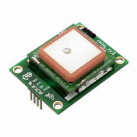
The Module is designed to mount horizontally, so the antenna can face to the sky. Screw holes are
located on each corner for more solid mounting if the user desires.
The Module must be used outdoors or with a clear view of the sky in order for it to fix on
satellites - this is the nature of GPS and not a limitation of our product. With an unobstructed,
clear view of the sky, GPS works anywhere in the world, 24 hours a day, seven days a week. Please
note that some products, such as motors, computers, and wireless/RF devices, which emit high levels
of magnetic field and interference, may prevent the Module from receiving the required GPS signals
from the satellites and may cause the performance of the Module to decrease. Additionally, when
using the Module in automobile applications, the optimal position for the Module is mounted on the
rooftop of the vehicle. If the Module is to be used inside the car, ensure that the Module’s antenna still
has a clear view of the sky, such as by placing it on the dashboard, and is not blocked by any metal
objects within the car.
Pin
1
2
3
4
Programmable Parallax SX/B microprocessor and open-source control firmware for advanced
users (not supported by Parallax, but offered as a download from the Parallax web site)
Pin Name
GND
VCC
SIO
/RAW
Type
G
P
I
I/O
Function
System ground. Connect to power supply’s ground (GND) terminal.
System power, +5V DC input.
Serial communication (commands sent TO the Module and data
received FROM the Module). Asynchronous, TTL-level interface,
4800bps, 8 data bits, no parity, 1 stop bit, non-inverted.
Mode select pin. Active LOW digital input. Internally pulled HIGH by
default. When the /RAW pin is unconnected, the default “Smart Mode” is
enabled, wherein commands for specific GPS data can be requested
and the results will be returned (see the “Command Structure” section
for more details). When /RAW is pulled LOW, the Module will enter
“Raw Mode” and will transmit standard strings, allowing advanced users
to use the raw GPS data directly.
Page 2/11
Related parts for 28146
Image
Part Number
Description
Manufacturer
Datasheet
Request
R


Part Number:
Description:
Microcontroller Modules & Accessories DISCONTINUED BY PARALLAX
Manufacturer:
Parallax Inc

Part Number:
Description:
BOOK UNDERSTANDING SIGNALS
Manufacturer:
Parallax Inc
Datasheet:


Part Number:
Description:
COMPETITION RING FOR SUMOBOT
Manufacturer:
Parallax Inc
Datasheet:


Part Number:
Description:
TEXT INFRARED REMOTE FOR BOE-BOT
Manufacturer:
Parallax Inc
Datasheet:
Part Number:
Description:
BOARD EXPERIMENT+LCD NX-1000
Manufacturer:
Parallax Inc
Datasheet:

Part Number:
Description:
CONTROLLER 16SERVO MOTOR CONTROL
Manufacturer:
Parallax Inc
Datasheet:

Part Number:
Description:
BASIC STAMP LOGIC ANALYZER
Manufacturer:
Parallax Inc
Datasheet:

Part Number:
Description:
IC MCU 2K FLASH 50MHZ SO-18
Manufacturer:
Parallax Inc
Datasheet: