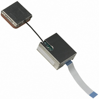
RGPSM002WA Semtech, RGPSM002WA Datasheet - Page 8

RGPSM002WA
Manufacturer Part Number
RGPSM002WA
Description
MODULE GPS RECEIVER LOW POWER
Manufacturer
Semtech
Datasheet
1.RGPSD012.pdf
(26 pages)
Specifications of RGPSM002WA
Frequency
1.575GHz
Sensitivity
-143dBm
Modulation Or Protocol
GPS
Applications
Automotive, Laptop, PDA
Current - Receiving
19mA
Data Interface
Connector, 16 Contact Board to Board
Voltage - Supply
2.7 V ~ 3.6 V
Package / Case
Module
Lead Free Status / RoHS Status
Contains lead / RoHS non-compliant
Features
-
Operating Temperature
-
Memory Size
-
Data Rate - Maximum
-
Antenna Connector
-
Notes on TTFF / start-up condition:
5.2.1
The simplest and easiest way to operate the RGPSM002 is the stand-alone configuration described below. In this case,
the GPS receiver is simply controlled by its main power supply. It only sends NMEA strings through its TXA line. The
data interface should be connected as follows:
Turning the main supply VCC on and off will switch the module into Active or Power-Down modes (see Figure 3 above).
When turned on, after the internal power-up sequence, the RGPSM002 will send the NMEA sentences through its TXA
pin. In this configuration, the serial port settings, the type of NMEA sentences, and the output rate are those defined in
Flash in the Default Parameters Table (see Section 6 below). No other initialization is required.
5.2.2
This is a slightly more elaborate way to operate the RGPSM002. Compared to Paragraph 5.2.1, the module can receive
command/data ASCII character strings from its RXA serial line. In this case the RXA line should be connected to a host,
microcontroller, or any other device that can send NMEA strings through a UART
Turning the main supply VCC on and off will switch the module into Active or Power-Down modes (see Figure 3 above).
When turned on, after the internal power-up sequence, the RGPSM002 will send the NMEA sentences through its TXA
pin. In this configuration, the serial port settings, the type of NMEA sentences, and the output rate are those defined in
Flash in the Default Parameters Table (see Section 6 below). These parameters can then be temporarily modified by
© Semtech 2005
•
•
Pin
1
2
3
4
5
6
7
8
9
10
11
12
14
16
Pin
5
When switching from Power Save or Stand-by to Active mode, the start up condition will be
When switching from Power Down to Stand-by then to Active mode, the start up condition will be
Operating the GPS receiver in a basic “stand-alone” configuration
Operating the GPS receiver in a basic “serial, bidirectional” configuration
o
o
o
o
o
o
Name
GND
ON/OFF
VCC
USPED
RXA
VRTCBK
TXA
PPS
GND
RESETN
ALMRDY
STY1
DELPOSN
STANDBYN
Name
RXA
Hot start if Almanac is valid, Ephemeris is valid (less than 4 hours old), approximate position is known
and RTC is valid
Warm start if Almanac is valid, Ephemeris is not valid, approximate position is known and RTC is valid
Cold start otherwise
Hot start if Almanac is valid, Ephemeris is valid (less than 4 hours old), approximate position is known
and RTC is valid
Warm start if the Almanac and approximate position saved in Flash are valid, and RTC is valid
Cold start otherwise
Table 5 - Basic data interface to operate the receiver in “serial, bidirectional” configuration
Table 4 – Basic data interface to operate the receiver in “stand-alone” configuration
Connection
To Ground
To VCC or N.C.
To the main power supply, turned on to operate the receiver, off to stop it
To VCC or N.C.
To VCC or N.C
To the back-up supply for the RTC
To the host interface, microcontroller, or other device that read the NMEA
strings
N.C.
To Ground
To VCC or N.C.
N.C.
N.C.
To VCC or N.C.
To VCC or N.C.
Connection
To the host, microcontroller, or other device that send the NMEA strings
Other pins similar to Table 4 above
8
RGPSM002
GPS Receiver
www.semtech.com


