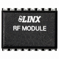
RXM-869-ES_ Linx Technologies Inc, RXM-869-ES_ Datasheet - Page 3

RXM-869-ES_
Manufacturer Part Number
RXM-869-ES_
Description
RECEIVER RF 869MHZ 16PIN SMD
Manufacturer
Linx Technologies Inc
Series
-r
Specifications of RXM-869-ES_
Frequency
869MHz
Sensitivity
-102dBm
Data Rate - Maximum
56 kbps
Modulation Or Protocol
FM, FSK
Current - Receiving
6.5mA
Data Interface
PCB, Surface Mount
Antenna Connector
PCB, Surface Mount
Voltage - Supply
4.5 V ~ 5.5 V
Operating Temperature
0°C ~ 70°C
Package / Case
16-SMD
Board Size
20.6 mm x 16 mm x 3.2 mm
Minimum Operating Temperature
0 C
Supply Voltage (min)
4.5 V
Product
RF Modules
Maximum Frequency
869.85 MHz
Supply Voltage (max)
5.5 V
Maximum Operating Temperature
+ 70 C
Applications
-
Memory Size
-
Features
-
Lead Free Status / RoHS Status
Lead free / RoHS Compliant
Features
-
Applications
-
Memory Size
-
Lead Free Status / Rohs Status
Lead free / RoHS Compliant
Other names
RXM-869-ES
RXM-869-ES
RXM-869-ES
Available stocks
Company
Part Number
Manufacturer
Quantity
Price
Company:
Part Number:
RXM-869-ES_
Manufacturer:
LNX
Quantity:
25
PIN ASSIGNMENTS
Figure 7: ES Series Receiver Pinout (Top View)
PIN DESCRIPTIONS
Page 4
Pin #
15 - 16
6 - 9
10
11
12
13
14
1
2
3
4
5
Name
AUDIO
A REF
DATA
RSSI
GND
GND
ANT
PDN
V
NC
NC
NC
CC
Received Signal Strength Indicator. This line will supply an
Digital Data Output. This line will output the demodulated
analog voltage that is proportional to the strength of the
Power Down. Pulling this line low will place the receiver
No Electrical Connection. Soldered for physical support
No Electrical Connection. Soldered for physical support
No Electrical Connection. Soldered for physical support
into a low-current state. The module will not be able to
1
2
3
4
5
6
8
7
Audio RMS (Average) Voltage Reference
ANT
GND
NC
GND
VCC
NC
NC
NC
receive a signal in this state.
Recovered Analog Output
AUDIO
A REF
DATA
RSSI
PDN
50-ohm RF Input
Description
received signal.
NC
NC
NC
Analog Ground
Analog Ground
Supply Voltage
digital data.
only.
only.
only.
16
15
14
13
12
10
11
9
MODULE DESCRIPTION
Figure 8: ES Series Receiver Block Diagram
THEORY OF OPERATION
RF In
The RXM-***-ES module is a single-channel receiver designed for the wireless
reception of digital or analog information over distances of up to 1,000 feet
outdoors and up to 500 feet indoors. It is based on a high-performance,
synthesized, single conversion, superhet architecture. FM / FSK modulation and
SAW filtering are utilized to provide performance and noise immunity that are
superior to AM-based solutions. The ES series is incredibly compact and cost-
effective when compared with other FM / FSK devices. Best of all, it is packed
with many useful features, offering a great deal of design flexibility.
The receiver operates in a single conversion superhet configuration, with an IF
of 10.7MHz and a baseband analog bandwidth of 28kHz. It is capable of
receiving a signal as low as -97dBm (typical). The signal is filtered at the front
end by a SAW band-pass filter. The filtered signal is then amplified and down-
converted to the 10.7MHz IF by mixing it with a LO frequency generated by a
PLL-locked VCO. The 10.7MHz IF is then amplified and filtered. Finally, a PLL
demodulator is used to recover the baseband analog signal from the carrier. This
analog signal is low-pass filtered and then output on the AUDIO line.
The analog output can be individual frequencies or complex waveforms, such as
voice or music. The AUDIO line can also be used to recover unsquared data in
instances where a designer wishes to use an external data slicer.
The ES receiver also features a high-performance on-board data slicer for
recovery of data transmission. Its output is internally derived from the filtered
analog baseband, which is squared and made externally available on the DATA
line. The data slicer is capable of recreating squared waveforms from 100Hz to
28kHz, giving a data rate bandwidth of 200bps to 56kbps.
It is important to note that this receiver does not provide hysteresis or squelching
of the DATA line. This means that in the absence of a valid transmission or
transitional data, the DATA line will switch randomly. The effects of this noise
must be considered and will be discussed in further detail later in this guide.
The receiver features a Received Signal Strength Indicator (RSSI) output. The
RSSI pin outputs a linear voltage relative to the incoming signal level. This output
has many valuable uses, including interference assessment, signal strength
indication, external data squelching and qualification, and transmitter presence
indication. Since RSSI values vary from part to part and correspond to signal
strength and not necessarily distance, it is not recommended for range-finding
applications.
SAW BPF
Precision
Crystal
LNA
PLL Frequency
Synthesizer
10.7MHz
IF Filter
Detector
Limiter
Peak
Demodulator
PLL
Slicer
Data
Output
Output
Output
Audio
RSSI
Data
Page 5


