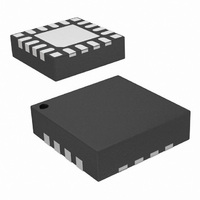
SI4311-B10-GM Silicon Laboratories Inc, SI4311-B10-GM Datasheet - Page 11

SI4311-B10-GM
Manufacturer Part Number
SI4311-B10-GM
Description
IC RX FSK 315/434MHZ 20VQFN
Manufacturer
Silicon Laboratories Inc
Series
EZRadio®r
Type
ISM Receiverr
Datasheets
1.SI4311-B10-GM.pdf
(20 pages)
2.SI4311-B10-GM.pdf
(2 pages)
3.SI4311-B10-GM.pdf
(20 pages)
Specifications of SI4311-B10-GM
Package / Case
20-VQFN
Frequency
315MHz, 434MHz
Sensitivity
-104dBm
Data Rate - Maximum
10 kBaud
Modulation Or Protocol
FSK
Applications
Garage Openers, RKE, Security Alarms
Data Interface
PCB, Surface Mount
Antenna Connector
PCB, Surface Mount
Voltage - Supply
2.7 V ~ 3.6 V
Operating Temperature
-40°C ~ 85°C
Operating Frequency
315 MHz to 434 MHz
Operating Supply Voltage
2.7 V to 3.6 V
Maximum Operating Temperature
+ 95 C
Minimum Operating Temperature
- 45 C
Mounting Style
SMD/SMT
Supply Current
20 mA
Lead Free Status / RoHS Status
Lead free / RoHS Compliant
Features
-
Memory Size
-
Current - Receiving
-
Lead Free Status / Rohs Status
Lead free / RoHS Compliant
Other names
336-1976-5
3.5. Frequency Deviation Selection
In order to accommodate wide frequency deviation ranges, the Si4311 FSK receiver uses two input pins, pins 16
and 17, to select a range of frequency deviations as shown in Table 10. For example, if the FSK signal has a
frequency deviation (F) of 50 kHz, then the DEV[1:0] = (0,1) or pin 16 = 0 and pin 17 = 1.
3.6. Automatic Frequency Centering (AFC)
The channel bandwidth directly affects the sensitivity of any wireless receiver. Typical analog FSK receivers use an
external ceramic filter with a large bandwidth to accommodate the data rate, frequency deviation, crystal
tolerances, and transmit carrier frequency offsets, which leads to unnecessary amounts of noise and lower
sensitivity levels. The Si4311 uses a narrow channel bandwidth of 200 kHz and automatic frequency centering
(AFC) to obtain excellent sensitivity levels (–104 dBm at data rate of 5 kbps at 315 MHz) while still accommodating
up to ±200 kHz of frequency tracking from its center frequency.
In the ideal case of no transmit carrier frequency errors or receiver frequency errors, both FSK tones for a logic "1"
and "0" from the transmitter appear in the receiver IF channel bandwidth as shown in Figure 5 (a). However, if the
transmitter has a large carrier offset such as shown in Figure 5 (b), then only one of the FSK tones falls in the
receiver channel bandwidth and thus the receiver produces errors. The standard approach to resolving this
problem is to use an IF channel filter that is large enough to accommodate the transmitter frequency error, but this
leads to degraded sensitivity. The Si4311 uses AFC to re-center the channel bandwidth about the two FSK tones
as shown in Figure 5 (c) to maintain excellent sensitivity with a small IF channel filter. The algorithm requires one
FSK tone to be in-band and at most three alternating sequences of 0/1 data typically found in a preamble plus
700 µs of fixed delay time (approximately 230 µs per 0/1 data pair) to re-center the IF bandwidth. Worst case
acquisition time is 1.3 ms for a data rate of 10 kbps.
The AFC algorithm includes a 200 ms hold time. The device holds the frequency found by the AFC algorithm for a
time of 200 ms after no RF signal activity before restarting the frequency search. This allows a frequency found in
the first packet of transmission to be held for any subsequent retransmissions of packets if the retransmissions
occur before 200 ms. This hold frequency ensures all bits of the second and subsequent packets are recovered
completely. The AFC frequency search resumes after 200 ms of no RF signal activity.
The AFC algorithm can be disabled by setting the logic level on pin 5 to a logic zero as shown in Table 11.
Figure 5. (a) Ideal case (b) Scenario with Tx Offset (c) Si4311 AFC Re-Centers IF BW
200kHz
IF BW
(a)
DEV1 (pin 16)
Table 10. Frequency Deviation Range Settings
0
0
1
1
DEV0 (pin 17)
0
1
0
1
TX OFFSET 100kHz
Rev. 0.5
(b)
Frequency Deviation [kHz]
30 < ∆F ≤ 50
50 < ∆F ≤ 70
70 < ∆F ≤ 90
1 < ∆F ≤ 30
TX OFFSET 100kHz
(c)
Si4311
11


