OTX-433-HH-KF3-MS Linx Technologies Inc, OTX-433-HH-KF3-MS Datasheet - Page 2
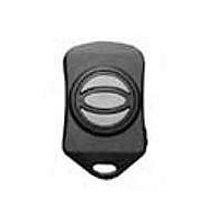
OTX-433-HH-KF3-MS
Manufacturer Part Number
OTX-433-HH-KF3-MS
Description
XMITTER KEYFOB 433MHZ 3 BUTTON
Manufacturer
Linx Technologies Inc
Datasheet
1.OTX-315-HH-KF5-MS.pdf
(5 pages)
Specifications of OTX-433-HH-KF3-MS
Function
Transmitter
Frequency
433MHz
Applications
Keyless Entery, Home Automation, Wireless Audio/Video
Interface
Handheld, 3 Button
Data Rate - Maximum
9.6 kbps
Features
3 buttons, 1000 ft. Operating Distance
Voltage - Supply
2.1 V ~ 3.6 V
Package / Case
Keyfob
Board Size
56.6 mm x 34.8 mm x 11.4 mm
Minimum Operating Temperature
- 40 C
Supply Voltage (min)
2.1 V
Product
RF Modules
Maximum Frequency
433.92 MHz
Supply Voltage (max)
3.6 V
Supply Current
3.4 mA
Maximum Operating Temperature
+ 85 C
Lead Free Status / RoHS Status
Lead free / RoHS Compliant
Power - Output
-
Sensitivity
-
Modulation Or Protocol
-
Lead Free Status / Rohs Status
Lead free / RoHS Compliant


Notes
1. Characterized, but not tested.
THEORY OF OPERATION
Page 2
ELECTRICAL SPECIFICATIONS
Parameter
POWER SUPPLY
Operating Voltage
Supply Current
Power-Down Current
TRANSMITTER SECTION
Transmit Frequency Range:
Center Frequency Accuracy
Data Rate
ENVIRONMENTAL
Operating Temperature Range
OTX-315-HH-KF#-MS
OTX-418-HH-KF#-MS
OTX-433-HH-KF#-MS
The MS Series Keyfob Transmitter combines a high-performance synthesized
transmitter with an on-board MS Series encoder IC to form a highly reliable, yet
cost-effective RF remote control transmitter. The transmitter’s advanced
synthesized architecture delivers superior stability and frequency accuracy while
minimizing the effects of temperature and body proximity.
The advanced MS Series encoder has several advantages over previous
solutions. It provides more security by offering 2
orders of magnitude greater than older encoders. Furthermore, the address is
instantly established with a simple button press, eliminating cumbersome DIP
switches and cut traces. When paired with a MS Series decoder, keyfob identity
can be determined and distinct transmitter-receiver relationships established.
The Keyfob operates in the following manner: when a button is pressed on the
Keyfob, power is applied to the internal circuitry and the encoder IC is enabled.
The encoder then detects the logic states of the button data lines. The encoder
data is used to modulate the transmitter, which, through the antenna, conveys
the data into free space. The transmission cycle continues until the button is
released. On the receiver side, a MS Series decoder IC is used to check the
transmitter’s address bits against the address saved in memory. If a match is
confirmed, and if the decoder has permission to recognize the specific button
being pressed, the decoder’s outputs are set to replicate the transmitter’s button
states. These outputs can then be used to activate external circuitry required by
the application.
The transmitter is compatible with the LT and LR product families. For
applications where range is critical, the LR Series receiver is the best choice due
to its outstanding sensitivity. When the Keyfob transmitter is combined with an
LR Series receiver and MS Series decoder, ranges of up to 750 feet are
possible. Applications operating over shorter distances will also benefit from the
increased link reliability and superior noise immunity provided by the LR receiver.
Designation
V
I
I
PDN
F
CC
–
–
–
CC
C
Min.
2.1
-50
-40
–
–
–
–
–
–
Typical
433.92
9,600
315
418
3.0
3.4
5.0
–
–
24
addresses, which is several
Max.
+50
+85
3.6
–
–
–
–
–
–
Units
VDC
MHz
MHz
MHz
kHz
mA
bps
nA
°
C
Notes
–
–
1
–
–
–
–
–
1
SETTING THE TRANSMITTER ADDRESS
BUTTON ASSIGNMENTS
Figure 3: OTX-***-HH-KF#-MS Button Assignments
The Keyfobs are all supplied from the
factory with a default address and all
buttons authorized. The address is
changed by using a paper clip or probe
to press the CREATE_ADDR button on
the board through the hole in the back
of the case. When the button is
depressed, a LED will light up in the
MODE_IND window, indicating that the
address is being created. The address
will be randomized for as long as the
button is held down. When the button is
released, the randomized address is saved and the LED will begin flashing to
indicate that the Control Permissions may now be set. Press the buttons that the
Keyfob user will have the authority to access. Press the CREATE_ADDR button
with the paper clip again or wait 17 seconds for it to time out. The address and
Control Permissions are now set. The decoder will need to learn the address
before it will accept any transmissions. Please see the Typical Applications
section of this data guide or the MS Series Decoder Data Guide for details.
The Keyfob is available in five button configurations. Those configurations and
the corresponding switch numbers are shown in the figure below. The table
shows which encoder data line has been assigned to each switch. When a
button is pressed, the data line will go high, causing the corresponding data line
on the decoder to go high if the address has been learned.
S1
S5
S4
S2
S3
S1
S4
S2
S4
S5
S2
S3
Figure 2: CREATE_ADDR Button Access
Button
S1
S2
S3
S4
S5
S4
S5
S2
CREATE_ADDR
Button Access
Data Line
D0
D1
D2
D3
D4
Page 3
Related parts for OTX-433-HH-KF3-MS
Image
Part Number
Description
Manufacturer
Datasheet
Request
R

Part Number:
Description:
TRANSMITTER 433MHZ MS SERIES
Manufacturer:
Linx Technologies Inc
Datasheet:

Part Number:
Description:
TRANSMITTER 433MHZ MS SER LNG-RG
Manufacturer:
Linx Technologies Inc
Datasheet:

Part Number:
Description:
XMITTER KEYFOB 433MHZ 5 BUTTON
Manufacturer:
Linx Technologies Inc
Datasheet:

Part Number:
Description:
XMITTER KEYFOB 433MHZ 1 BUTTON
Manufacturer:
Linx Technologies Inc
Datasheet:

Part Number:
Description:
XMITTER KEYFOB 433MHZ 2 BUTTON
Manufacturer:
Linx Technologies Inc
Datasheet:

Part Number:
Description:
XMITTER KEYFOB 433MHZ 4 BUTTON
Manufacturer:
Linx Technologies Inc
Datasheet:

Part Number:
Description:
XMITTER HS LNG-RANGE 433MHZ 8BTN
Manufacturer:
Linx Technologies Inc
Datasheet:
Part Number:
Description:
RF Modules & Development Tools HS 8Button Compact Handhld Trans 433MHz
Manufacturer:
Linx Technologies Inc
Datasheet:

Part Number:
Description:
HOLDER BATTERY 20MM COIN CR2032
Manufacturer:
Linx Technologies Inc
Datasheet:

Part Number:
Description:
CONN RPSMA BL CRJA-CPV 8.5" COAX
Manufacturer:
Linx Technologies Inc

Part Number:
Description:
MODULE USB LOW SPEED
Manufacturer:
Linx Technologies Inc
Datasheet:

Part Number:
Description:
IC TRANSCODER MT BI-DIR 20-SSOP
Manufacturer:
Linx Technologies Inc
Datasheet:

Part Number:
Description:
IC ENCODER LOW SECURITY 8DIP
Manufacturer:
Linx Technologies Inc
Datasheet:

Part Number:
Description:
IC DECODER MS SERIES 20-SSOP
Manufacturer:
Linx Technologies Inc
Datasheet:
Part Number:
Description:
IC ENCODER MS SERIES 20-SSOP
Manufacturer:
Linx Technologies Inc
Datasheet: