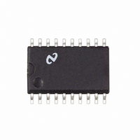
LM1865M National Semiconductor, LM1865M Datasheet - Page 9

LM1865M
Manufacturer Part Number
LM1865M
Description
IC ADVANCED FM IF SYSTEM SO20
Manufacturer
National Semiconductor
Datasheet
1.LM1865N.pdf
(16 pages)
Specifications of LM1865M
Function
FM IF System
Rf Type
FM
Package / Case
20-SOIC (0.300", 7.50mm Width)
Lead Free Status / RoHS Status
Contains lead / RoHS non-compliant
Other names
*LM1865M
Available stocks
Company
Part Number
Manufacturer
Quantity
Price
Company:
Part Number:
LM1865M
Manufacturer:
NSC
Quantity:
5 510
Part Number:
LM1865M
Manufacturer:
NS/国半
Quantity:
20 000
Application Notes
The LM1865 has been carefully designed to insure low AFT
offset current at the point of minimum THD AFT offset cur-
rent will cause a non-symmetric deviation mute stop win-
dow about the point of minimum THD No external AFT off-
set adjustment should be necessary with the LM1865 The
amount of resistance in series with the 18
coil drive inductor L1 has a significant effect on the mini-
mum THD This series resistance is contributed not only by
R13 but also by the Q of L1 The Q of L1 should be as high
as possible (ie Q
lems with the Q variation of L1 Once R13 has been opti-
mized for minimum THD adjustment on a radio by radio
basis should be un-necessary
DUAL THRESHOLD AGC
(AUTOMATIC LOCAL DISTANCE SWITCH)
There is a well recognized need in the field for gain reducing
(AGCing) the front end (tuner) of an FM receiver This gain
reduction is important in preventing overload of the front
end which might occur for large signal inputs Overloading
the front end with two out-of-band signals one channel
spacing apart and one channel spacing from center fre-
quency or two channel spacings apart and two channel
spacings from center frequency will produce a third order
intermodulation product (IM
product can completely block out a weaker desired station
The AGC in the LM1865 has been specially designed to
deal with the problem of IM
l
50) in order to avoid production prob-
3
3
) which falls inband This IM
(Continued)
H quadrature
FIGURE 5 Dual Threshold AGC
I
otherwise I
Gm
I
V
1
AGC
o l
e
1
GM
e
V
V
WB
WB
Gm
1
V
1
e
otherwise I
2
m
e
V
3
constants
only if V
o
0
where Gm
9
AGC
m l
With the LM1865 system a low AGC threshold is achieved
whenever there are strong out-of-band signals that might
generate an interfering IM
old is achieved if there are no strong out-of-band signals
The high AGC threshold allows the receiver to obtain its
best signal-to-noise performance when there is no possibili-
ty of an IM
weaker desired stations to be received without gain-reduc-
ing the tuner It should be noted that when the AGC thresh-
old is set low there will be a signal-to-noise compromise
but is assumed that it is more desirable to listen to a slightly
noisy station than to listen to an undesired IM
simplified circuit diagram ( Figure 5 ) of the AGC system
shows how the dual AGC thresholds are achieved
V
fined as V
the ‘‘narrow band threshold’’ V
fixed tuner output which can either be an in-band or out-of-
band signal This fixed tuner output will be called the ‘‘wide
band threshold’’ Always V
the AGC time constant A reverse AGC system is shown
This means that V
The LM1865 AGC output is an open-collector current
source capable of sinking at least 1 mA
m
e
2
1V
e
0
e
I
1
1V corresponds to a fixed in-band signal level (de-
26 mV and
NB
3
) at the tuner output V
product The low AGC threshold allows for
AGC
decreases to gain-reduce the tuner
3
WB l
product and a high AGC thresh-
WB
V
NB
NB
also corresponds to a
will be referred to as
R11 and C13 define
TL H 7509 – 9
3
product The


