ATAKSTK512-3 Atmel, ATAKSTK512-3 Datasheet
ATAKSTK512-3
Specifications of ATAKSTK512-3


Related parts for ATAKSTK512-3


ATAKSTK512-3 Summary of contents
Page 1
... STK512 .................................................................................................................... AVR-based Uni-directional Radio Starter Kit Featuring Secure Rolling-Code RF Transmission Encryption User Guide Note: This Radio Starter Kit is not self-contained based on an Atmel Flash Microcontroller Starter Kit that must be obtained separately. ® ® ® AVR STK 500 5170C–AVR–10/09 ...
Page 2
Table of Contents Section 1 Introduction................................................................................................................. 1-1 1.1 Purpose.............................................................................................................................. 1-1 1.2 General Description ........................................................................................................... 1-1 1.3 Evaluation Kit Features...................................................................................................... 1-1 1.4 Included in the Kit .............................................................................................................. 1-2 Section 2 Getting Started ........................................................................................................... 2-1 2.1 Hardware Assembly........................................................................................................... 2-1 2.2 Initial Programming ...
Page 3
... Congratulations on your purchase of the Atmel Secure Rolling Code RF Transmission Encryption. This kit uses an Atmel STK troller Starter Kit that must be obtained separately. This User’s Guide describes how to use this Starter Kit. Section 2, Getting Started, describes how to assemble and program the hardware to demonstrate a wireless link that uses a secure rolling code algo- rithm ...
Page 4
... Included in the Kit Note: This Radio Starter Kit is not self-contained based on an Atmel STK500 Flash Microcontroller Starter Kit that must be obtained separately. This starter kit includes all the essential components needed to demonstrate an AVR-based uni-direc- tional radio that features a Secure Rolling-Code RF Transmission Encryption protocol. Contents of this ...
Page 5
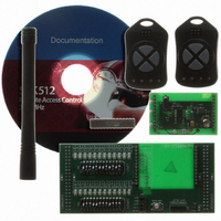
Figure 1-1. Kit Contents For investigating further capabilities of this kit, the following are optional: JTAGICE mkII for debugging IAR Embedded Workbench porting it to another compiler (precompiled source code with default configuration is provided on the CDROM). STK512 User ...
Page 6
This section contains the steps required to get a simple system with a receiver and two transmitters up and running. Hardware assembly, initial programming of the components, teaching the transmitters to the receiver, and demonstrating the transmission protocol are described ...
Page 7
Getting Started 1. Carefully remove any ICs in the green “SCKT3200A2” socket. 2. Insert the furnished ATMega88 into the “SCKT3200A2” socket. Note: The orientation of the red stripe in the cable is not critical in the following steps as long ...
Page 8
Step B: Assemble and Attach the STK512 Interface Board The STK512 Interface Board must be assembled and mounted on the STK500 Board. The completed assembly is shown in Figure 2-3. Assembled STK512 Interface Board 1. Orient the STK500 as shown ...
Page 9
Getting Started Figure 2-4. STK512 Jumper Placement 2-4 5170C–AVR–10/09 STK512 User Guide ...
Page 10
Step C: Mount the Receiver Application Board The Receiver Application Board must be mounted on the STK512 Interface Board. The completed assembly is shown in Figure 2-5. Completed Receiver Assembly Caution: After the next step, if the receiver board is ...
Page 11
Getting Started 2.2 Initial Programming After setting-up the hardware, insert the accompanying CD into the computer’s CDROM drive. Note: If you want to use something other than the pre-compiled demonstration software and EEPROM files included on the CD, there is ...
Page 12
Programming the Transmitter( the STK500, remove the 6-pin cable from the “SPROG2” header, plug it into the ISP program- ming adapter. Next, insert the transmitter application board into the adapter, as shown in Figure 2-6. Transmitter Key ...
Page 13
Getting Started 2.3 Teach the Transmitters to the Receiver In order for the rolling code to work, each transmitter must convey to (teach) the receiver three data ele- ments: its unique serial number, its secret key, and its sequence counter ...
Page 14
... Similar to the above approach, incremented counter values can be changed through manipulation of the counter value variable directly in software. Atmel recommends appropriate variable monitoring capabili- ties be available before attempting this approach. Whichever approach is used, the transmitter key fob and receiver counter can be resynchronized by having the receiver relearn the transmitter key fob ...
Page 15
The following describes optional programming that is not necessary to use the kit to demonstrate the roll- ing code algorithm over an RF link. In addition to the information below, the accompanying CD contains a “readme.html” file that documents user ...
Page 16
Programming Notes 3.2 Project Compilation This step can be skipped if you only want to use the precompiled source code with default settings. If not, compile projects for both the transmitter and the receiver. Detailed compilation instructions and fuse settings ...
Page 17
Table 4-1. Troubleshooting Solutions Problem Reason Power is not applied or is less than 5V DATA Selector switch was not set to the STK511 LED on Receiver position when power was applied Application Board not active Receiver in permanent sleep ...
Page 18
Troubleshooting Guide Table 4-1. Troubleshooting Solutions (Continued) Problem Reason STK512 Interface Board not correctly connected to STK500 ISP ribbon cable not connected properly Unable to load STK512 Interface Incorrect device selected Board firmware Device present in STK500 sockets ISP jumper ...
Page 19
... Disclaimer: The information in this document is provided in connection with Atmel products. No license, express or implied, by estoppel or otherwise, to any intellectual property right is granted by this document or in connection with the sale of Atmel products. EXCEPT AS SET FORTH IN ATMEL’S TERMS AND CONDI- TIONS OF SALE LOCATED ON ATMEL’S WEB SITE, ATMEL ASSUMES NO LIABILITY WHATSOEVER AND DISCLAIMS ANY EXPRESS, IMPLIED OR STATUTORY WARRANTY RELATING TO ITS PRODUCTS INCLUDING, BUT NOT LIMITED TO, THE IMPLIED WARRANTY OF MERCHANTABILITY, FITNESS FOR A PARTICULAR PURPOSE, OR NON-INFRINGEMENT ...