1004-TCB1D434 Silicon Laboratories Inc, 1004-TCB1D434 Datasheet - Page 7
1004-TCB1D434
Manufacturer Part Number
1004-TCB1D434
Description
BOARD EVALUATION FOR SI1004
Manufacturer
Silicon Laboratories Inc
Type
Transceiver, ISMr
Specifications of 1004-TCB1D434
Mfg Application Notes
SI1000 Code Examples AppNote
Frequency
434MHz
Supply Voltage (min)
0.9 V
Product
RF Modules
Maximum Frequency
915 MHz
Output Power
13 dBm
Antenna
SMA
Supply Voltage (max)
3.6 V
For Use With/related Products
Si100x
Lead Free Status / RoHS Status
Lead free / RoHS Compliant
Lead Free Status / RoHS Status
Lead free / RoHS Compliant, Lead free / RoHS Compliant
Other names
336-1889


3.7. Keil µVision2 and µVision3 Silicon Laboratories Drivers
As an alternative to the Silicon Laboratories IDE, the µVision debug driver allows the Keil µVision2 and µVision3
IDEs to communicate with Silicon Laboratories’ on-chip debug logic. In-system Flash memory programming
integrated into the driver allows for rapid updating of target code. The µVision2 and µVision3 IDEs can be used to
start and stop program execution, set breakpoints, check variables, inspect and modify memory contents, and
single-step through programs running on the actual target hardware. For more information, refer to the µVision
driver documentation. The documentation and software are available on the kit CD and from the downloads
webpage: www.silabs.com/mcudownloads.
4. Hardware Setup using a USB Debug Adapter
The motherboard is connected to a PC running the Silicon Laboratories IDE via the USB Debug Adapter as shown
in Figure 6.
1. Connect the USB Debug Adapter to the DEBUG connector on the motherboard with the 10-pin ribbon cable.
2. Connect one end of the USB cable to the USB connector on the USB Debug Adapter.
3. Verify that a shorting block is installed on J17 and that SW5 is in the ON position.
4. Connect the other end of the USB cable to a USB Port on the PC.
5. Connect the ac/dc power adapter to power jack P1 on the target board (Optional).
Notes:
Use the Reset button in the IDE to reset the target when connected using a USB Debug Adapter.
Remove power from the target board and the USB Debug Adapter before connecting or disconnecting the
ribbon cable from the target board. Connecting or disconnecting the cable when the devices have power can
damage the device and/or the USB Debug Adapter.
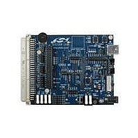
Motherboard with Daughtercard Attached
H1
R15
J15
J18
J19
J20
J16
P4
SILICON LABS
www.silabs.com
J5
VDD/DC+
J3
J6
TOUCH SENSE SWITCH
J7
P0.6
Figure 6. Hardware Setup using a USB Debug Adapter
`
OFF
ON
J2
J13
J14
SW5
J4
J8
P1.6
P1.5
IMEASURE
AAA_BAT
RESET
COIN_CELL
WALL_PWR
J17
H2
USB POWER
P0.2
+1VD
+3VD
VBAT
J11
2103
VBAT
J1
U3
CP
P0.3
J12
P2
P3
SW4
J9
Rev. 0.1
USB Debug
Adapter
Adapter
AC/DC
Cable
USB
Si10xx-DK
PC
7
Related parts for 1004-TCB1D434
Image
Part Number
Description
Manufacturer
Datasheet
Request
R


Part Number:
Description:
BOARD EVALUATION FOR SI1004
Manufacturer:
Silicon Laboratories Inc
Datasheet:

Part Number:
Description:
RF Connectors OSSM CABLE JACK STRT BULKHEAD
Manufacturer:
Tyco Electronics


Part Number:
Description:
SMD/C�/SINGLE-ENDED OUTPUT SILICON OSCILLATOR
Manufacturer:
Silicon Laboratories Inc
Part Number:
Description:
Manufacturer:
Silicon Laboratories Inc
Datasheet:
Part Number:
Description:
N/A N/A/SI4010 AES KEYFOB DEMO WITH LCD RX
Manufacturer:
Silicon Laboratories Inc
Datasheet:
Part Number:
Description:
N/A N/A/SI4010 SIMPLIFIED KEY FOB DEMO WITH LED RX
Manufacturer:
Silicon Laboratories Inc
Datasheet:
Part Number:
Description:
N/A/-40 TO 85 OC/EZLINK MODULE; F930/4432 HIGH BAND (REV E/B1)
Manufacturer:
Silicon Laboratories Inc
Part Number:
Description:
EZLink Module; F930/4432 Low Band (rev e/B1)
Manufacturer:
Silicon Laboratories Inc