CY3271-EXP1 Cypress Semiconductor Corp, CY3271-EXP1 Datasheet
CY3271-EXP1
Specifications of CY3271-EXP1


Related parts for CY3271-EXP1


CY3271-EXP1 Summary of contents
Page 1
... CY3271-EXP1 PSoC ® Environmental Sensing Kit Spec. # 001-49259 Rev. ** Cypress Semiconductor San Jose, CA 95134-1709 Phone (USA): 800.858.1810 Phone (Intnl): 408.943.2600 http://www.cypress.com 198 Champion Court ...
Page 2
... Code protection does not mean that we are guaranteeing the product as "unbreakable." Cypress is willing to work with the customer who is concerned about the integrity of their code. Code protection is constantly evolving Cypress are committed to continuously improving the code protection features of our products. 2 CY3271-EXP1 Environmental Sensing Kit, Spec. # 001-49259 Rev. ** ...
Page 3
... Contents 1. Introduction 1.1 Welcome ......................................................................................................................5 1.2 CY3271-EXP1 System Overview ................................................................................5 1.2.1 CY3271-EXP1 Hardware Overview .................................................................5 1.2.2 CY3271-EXP1 Software Overview...................................................................6 1.3 Document Revision History .......................................................................................8 1.4 Documentation Conventions .......................................................................................9 2. Installation Guide 2.1 CY3271 Installation Instructions ................................................................................11 3. Design Examples 3.1 Design Example Summary Table 3.2 Out of Box Design Examples.....................................................................................17 3 ...
Page 4
... Contents iv CY3271 EXP1 Environmental Sensing Kit, Spec. # 001-49259 Rev. ** ...
Page 5
... PSoC's flexible analog to allow multiple sensors to connect the same internal resources ■ If you have questions about or need help with the CY3271-EXP1 kit, visit our online support center at http://www.cypress.com/support representative or authorized distributor. 1.2 CY3271-EXP1 System Overview 1 ...
Page 6
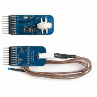
... RF Expansion Board to read the sensor. Figure 1-2. Pigtail Thermistor Expansion Board 1.2.2 CY3271-EXP1 Software Overview The software noted in this section is not included in the CY3271-EXP1 Kit, but instead, is located on the CY3271 PSoC FirstTouch Starter Kit CD. 1.2.2.1 PSoC Designer PSoC Designer is the integrated development environment (IDE) where all PSoC projects are cre- ated, edited, built, and debugged ...
Page 7
... Figure 1-3. PSoC Designer 1.2.2.2 PSoC Programmer After a PSoC project is built, the PSoC Programmer tool (along with the PC Bridge board) programs the target PSoC. Figure 1-4. PSoC Programmer CY3271 EXP1 Environmental Sensing Kit, Spec. # 001-49259 Rev. ** Introduction 7 ...
Page 8
... SCD enables data logging and monitoring of wired and wireless sensors created using PSoC. The features include data logging, calibration, alarms, and data aggregation from hundreds of sensors. The CY3271-EXP1 Kit uses the SCD application to wirelessly log data from the sensors connected to the PC Bridge using the CY3271 PSoC FirstTouch Starter Kit. ...
Page 9
... Bold] File > Open Bold Times New Roman Text in gray boxes CY3271 EXP1 Environmental Sensing Kit, Spec. # 001-49259 Rev. ** Usage Displays file locations, user entered text, and source code: C:\ ...cd\icc\ Displays file names and reference documentation: Read about the sourcefile.hex file in the PSoC Designer User Guide. ...
Page 10
... Introduction 10 CY3271 EXP1 Environmental Sensing Kit, Spec. # 001-49259 Rev. ** ...
Page 11
... Installation Guide The CY3271-EXP1 uses the same software as the PSoC FirstTouch™ Starter kit. If you have installed the software for your FirstTouch kit, then no additional installation is necessary. If, however, you did not install the PSoC FirstTouch™ Starter kit then follow these instructions. ...
Page 12
... Installation Guide Figure 2-2. Kit Installer Click Install CY3271 Kit and Tools to start the kit installations. Click Next to start the installer and then choose Install to launch the PSoC Designer installer. Click Next through the next several screens. When the Device Driver screen appears, click Next and then Finish. ...
Page 13
... Wait for the Setup Status screen to complete. Then select Finish to complete the installation of PSoC Designer 5.0. Figure 2-4. Setup Status Screen The Hi-TECH compiler for PSoC Designer begins installation. Figure 2-5. Hi-TECH Compiler CY3271 EXP1 Environmental Sensing Kit, Spec. # 001-49259 Rev. ** Installation Guide 13 ...
Page 14
... The Sense and Control Dashboard Software setup wizard appears. Click Next through the next sev- eral screens to install the default configuration. This installer also installs Microsoft SQL server. Figure 2-7. Installing SCD Software 14 CY3271 EXP1 Environmental Sensing Kit, Spec. # 001-49259 Rev. ** ...
Page 15
... Design Example Summary Table on page The firmware section contains the firmware projects for all of the projects used in this kit. Each project contains the source code as well as the compiled .HEX image enabling you to quickly pro- CY3271 EXP1 Environmental Sensing Kit, Spec. # 001-49259 Rev. ** 21. Installation Guide ...
Page 16
... It is advised to generate and build each project before making changes to the project source code. The Hardware section contains the design files for the schematics and PCB layout. There are also in PDF format for ease of viewing. 16 CY3271 EXP1 Environmental Sensing Kit, Spec. # 001-49259 Rev. ** ...
Page 17
... Connect the RF Expansion Board to the PC Bridge. 2. Insert the PC Bridge into any free USB port of your PC/laptop. 3. Open PSoC Programmer, and load RF_I2C_Bridge.hex from the Hex Files folder located on the CY3271-EXP1 Kit CD. 4. Set Programming Mode to Reset, Device Family to 27x43, Device to CY8C27443 and click Program. ...
Page 18
... Attach the Weather Station Expansion Board and the battery pack to the RF Expansion board as shown in Figure 3-2. Figure 3-2. RF Expansion Board Connected to the Battery Pack and Weather Station Boards 7. Switch on power to the RF Expansion Board by sliding the ON/OFF switch on the battery pack towards the RF Expansion Board. 18 CY3271 EXP1 Environmental Sensing Kit, Spec. # 001-49259 Rev. ** ...
Page 19
... In the Manage Network screen, click Add to add a new node. ■ On the Node Binding screen, click Begin Binding. ■ Figure 3-5. Node Binding Window After activating this function, you have aproximately 20 seconds to press the bind button on the ■ RF Expansion Board. CY3271 EXP1 Environmental Sensing Kit, Spec. # 001-49259 Rev Design Examples 19 ...
Page 20
... Figure 3-7. Successful Bind Window 9. Click Next the Node Binding ( window. In this window, assign a name to the newly bound node. On the Node Configuration pane, click Load Node configuration from a file and load Weather_Station_Dashboard_Configuration.xml from the Configuration Files folder. 20 CY3271 EXP1 Environmental Sensing Kit, Spec. # 001-49259 Rev. ** ...
Page 21
... Figure 3-8. Node Configuration 10.Select graphical or textual mode of data display. The data is displayed in graphical or text format on the SCD screen. 11. Click Apply on all successive dialog boxes until the main SCD window reappears. CY3271 EXP1 Environmental Sensing Kit, Spec. # 001-49259 Rev. ** Design Examples 21 ...
Page 22
... On the Node Configuration pane, click the Load Node configuration from a file radio button and load Pigtail_Thermistor_Dashboard_Configureation.xml from the Configuration Files folder located on the CY3271-EXP1 Kit CD 10.Select graphical or textual mode of data display. The data is displayed in graphical or text format on the SCD screen. ...
Page 23
... PSoC sets the Board Ready line high to indicate to the PC Bridge that the values pre- sented are stable. Table 4-1. Weather Station Interface Definition Field Humidity Temperature Ambient Light Pressure CY3271 EXP1 Environmental Sensing Kit, Spec. # 001-49259 Rev slave device that presents the eight bytes of Size Format 16-bit 2's compliment 16-bit ...
Page 24
... PC Bridge. Table 4-2. Pigtail Thermistor Interface Definition Field Temperature (RF 16-bit EXP) Temperature (Pigtail) 16-bit 24 Size Format 2's compliment Degrees Celsius *10 2's compliment Degrees Celsius *10 CY3271 EXP1 Environmental Sensing Kit, Spec. # 001-49259 Rev. ** Units Byte Offset 0 2 ...
Page 25
... Figure 5-1. Configure Node Notepad.lnk 2. In the Configure Sensor dialog, specify: Sensor name ■ Sensor physical unit ■ Sensor data format ■ ■ Sensor bit range Scaling factor ■ Sensor display option ■ CY3271 EXP1 Environmental Sensing Kit, Spec. # 001-49259 Rev ...
Page 26
... Calibrating Sensors Click Apply. Figure 5-2. Adding a Sensor The sensor entry appears in the Configure Node dialog: Figure 5-3. Sensor Added Successfully Click Edit to start sensor editing. 26 CY3271 EXP1 Environmental Sensing Kit, Spec. # 001-49259 Rev. ** ...
Page 27
... SCD. SCD records both raw and calibrated data for each sensor in its data log. ■ The Calibrate Sensor window is where you calibrate the sensor. Figure 5-4. Calibrate Sensor Window CY3271 EXP1 Environmental Sensing Kit, Spec. # 001-49259 Rev. ** Calibrating Sensors 27 ...
Page 28
... You cannot change this name in SCD because this name is used to compare with the original for auto detect purpose. Node ID is automatically equal to sensor USB index + 0x40. USB sensors count connected to network, are shown in the status tray sensor and Next, on the second window, sensor nodeID is CY3271 EXP1 Environmental Sensing Kit, Spec. # 001-49259 Rev. ** ...
Page 29
... The Chart Options dialog provides a way to set low and high alarms for a selected sensor. This dia- log is activated using Tools > Selected Sensor > Chart Options or by selecting Chart Options in the toolbar. Figure 5-5. Chart Options for Setting Alarms CY3271 EXP1 Environmental Sensing Kit, Spec. # 001-49259 Rev. ** Calibrating Sensors 29 ...
Page 30
... The corresponding menu items is in the main menu at File > Export Data. 5.6 Saving a Configuration To save your network configuration, use File > Save Configuration or File > Save Configuration As. The network configuration is saved as an XML file. 30 CY3271 EXP1 Environmental Sensing Kit, Spec. # 001-49259 Rev. ** ...