ATAB5428-4-WB Atmel, ATAB5428-4-WB Datasheet - Page 22
ATAB5428-4-WB
Manufacturer Part Number
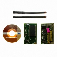
ATAB5428-4-WB
Description
KIT DEMO 434MHZ BLACKBIRD
Manufacturer
Atmel
Series
Smart RFr
Type
Transceiver, UHFr
Specifications of ATAB5428-4-WB
Frequency
434MHz
Maximum Frequency
434 MHz
Output Power
0 dBm to 10 dBm
Supply Voltage (max)
6 V
Supply Voltage (min)
3 V
Supply Current
21 mA
Maximum Operating Temperature
+ 85 C
Board Size
2 in x 3.5 in
Minimum Operating Temperature
- 40 C
Product
RF Modules
For Use With/related Products
ATA5428
Lead Free Status / RoHS Status
Lead free / RoHS Compliant
Other names
ATAB-5428-4-WB


Table 3-7.
3.13
22
Frequency (MHz) TX Current (mA) Output Power (dBm) R1 (k )
433.92
433.92
433.92
868.3
868.3
868.3
315
315
315
345
345
345
915
915
915
Output Power and TX Supply Current versus Supply Voltage and Temperature
ATA5423/ATA5425/ATA5428/ATA5429
Measured Output Power and Current Consumption with VS1 = VS2 = 3V, T
10.5
16.7
10.4
16.9
11.2
17.8
11.5
16.3
11.8
20.3
8.5
8.8
8.6
9.3
9.6
Table 3-8 on page 22
VS = VS1 = VS2 in the 433.92 MHz and 6.2 dBm case versus temperature and supply voltage
measured according to
opposed to the receiver sensitivity, the supply voltage has here the major impact on output
power variations because of the large signal behavior of a power amplifier. Thus, a two battery
system with voltage regulator or a 5V system shows much less variation than a 2.4V to 3.6V one
battery system because the supply voltage is then well within 3.0V and 3.6V.
The reason is that the amplitude at the output RF_OUT with optimum load resistance is
AVCC – 0.4V and the power is proportional to (AVCC – 0.4V)
changed. This means that the theoretical output power reduction if reducing the supply voltage
from 3.0V to 2.4V is 10 log ((3 V – 0.4 V)
ciple behavior in the measurement. This is not the same case for higher voltages, since here
increasing the supply voltage from 3V to 3.6V should theoretical increase the power by 1.8 dB;
but a gain of only 0.8 dB in the measurement shows that the amplitude does not increase with
the supply voltage because the load impedance is optimized for 3V and the output amplitude
stays more constant.
Table 3-8.
T
T
T
amb
amb
amb
VS =
=
= +25°C
= +85°C
–
40°C
Measured Output Power and Supply Current at 433.92 MHz, PWR_H = GND
10.5
10.7
10.2
-0.3
0.4
5.7
1.6
5.9
0.1
6.2
0.1
4.9
5.4
9.5
11
shows the measurement of the output power for a typical device with
Figure 3-10 on page 21
10.19 mA
10.62 mA
3.8 dBm
4.6 dBm
11.4 mA
3.9 dBm
2.4 V
56
27
27
56
27
27
56
22
22
33
15
22
33
15
15
VPWR_H
2
/(2.4 V – 0.4 V)
AVCC
AVCC
AVCC
AVCC
AVCC
GND
GND
GND
GND
GND
GND
GND
GND
GND
GND
with components according to
R
Lopt
2500
2400
2300
1170
1100
920
350
900
320
890
300
471
245
465
230
10.19 mA
11.19 mA
12.02 mA
5.5 dBm
6.2 dBm
5.5 dBm
2
3.0 V
( )
) = 2.2 dB.
L1 (nH)
amb
2
82
68
56
82
68
43
56
47
33
12
15
10
12
12
10
if the load impedance is not
= 25°C
Table 3-8
Q
28
32
35
75
74
65
40
38
43
58
54
57
62
62
60
L1
C1 (pF) C3 (pF)
10.78 mA
11.79 mA
12.73 mA
shows that prin-
6.2 dBm
7.1 dBm
6.6 dBm
0.75
4841D–WIRE–10/07
3.6 V
1.5
2.2
3.9
1.2
1.8
3.9
1.5
2.7
1.0
1.0
1.5
0.7
1.5
1.5
Table
3-7. As
3.3
0
0
0
0
0
0
0
0
0
0
0
0
0
0
Related parts for ATAB5428-4-WB
Image
Part Number
Description
Manufacturer
Datasheet
Request
R


Part Number:
Description:
KIT DEMO 868MHZ BLACKBIRD
Manufacturer:
Atmel
Datasheet:

Part Number:
Description:
BOARD BASESTATN UHF RCVR 433MHZ
Manufacturer:
Atmel
Datasheet:
Part Number:
Description:
BOARD BASESTATN UHF RCVR 868MHZ
Manufacturer:
Atmel
Datasheet:

Part Number:
Description:
DEV KIT FOR AVR/AVR32
Manufacturer:
Atmel
Datasheet:

Part Number:
Description:
INTERVAL AND WIPE/WASH WIPER CONTROL IC WITH DELAY
Manufacturer:
ATMEL Corporation
Datasheet:
Part Number:
Description:
Low-Voltage Voice-Switched IC for Hands-Free Operation
Manufacturer:
ATMEL Corporation
Datasheet:
Part Number:
Description:
MONOLITHIC INTEGRATED FEATUREPHONE CIRCUIT
Manufacturer:
ATMEL Corporation
Datasheet:
Part Number:
Description:
AM-FM Receiver IC U4255BM-M
Manufacturer:
ATMEL Corporation
Datasheet:
Part Number:
Description:
Monolithic Integrated Feature Phone Circuit
Manufacturer:
ATMEL Corporation
Datasheet:
Part Number:
Description:
Multistandard Video-IF and Quasi Parallel Sound Processing
Manufacturer:
ATMEL Corporation
Datasheet:
Part Number:
Description:
High-performance EE PLD
Manufacturer:
ATMEL Corporation
Datasheet: