APGAC031 Microchip Technology, APGAC031 Datasheet - Page 3
APGAC031
Manufacturer Part Number
APGAC031
Description
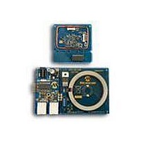
KIT ACC TIRE PRESSURE MON SYSTEM
Manufacturer
Microchip Technology
Type
Automotive, Tire Pressure Monitorr
Datasheet
1.APGAC031.pdf
(12 pages)
Specifications of APGAC031
Frequency
315MHz
Processor To Be Evaluated
PIC18F2680
Lead Free Status / RoHS Status
Lead free / RoHS Compliant
For Use With/related Products
APGRD003
Lead Free Status / Rohs Status
Lead free / RoHS Compliant


After application of power, the rfPIC microcontroller
executes an initialization procedure and goes into a
Sleep mode until a state change is detected on either
the SP-13 data line or the LF input. Either of these
inputs generates a wake-up, causing the rfPIC micro-
controller to transition into the Run mode. If the
wake-up was generated by the SP-13, the rfPIC micro-
controller reads the incoming data, assembles the data
into an appropriate message, and transmits the mes-
sage via the RF transmitter. Once the RF message is
sent, the rfPIC microcontroller reenters the Sleep
mode. If the wake-up was generated by the LF input,
the rfPIC microcontroller interprets the LF message,
executes the command and then reenters the Sleep
mode.
RF Circuitry
The PLL style transmitter within the rfPIC microcon-
troller requires minimum external components to com-
plete the RF transmitter. The fundamental frequency of
the transmitter is determined by Y1. To derive the
appropriate crystal frequency, simply divide the desired
transmit frequency by 32. For example, if the desired
transmit frequency is 315 MHz, the crystal frequency is
9.84375 MHz.
FIGURE 2:
© 2009 Microchip Technology Inc.
RF CIRCUITRY
Loop Antenna
L3
270 pF
C4
220Ω
R6
120 nH
22 pF
L2
C8
N. I.
R8
5 pF
C3
PS
ANT
Loop antenna L3 is matched to the single-ended RF
driver via C3 and C8, which also form the resonant tank.
Refer to application note AN831, “Matching Small Loop
Antennas to rfPIC
tion note AN868, “Designing Loop Antennas for the
rfPIC12F675” (DS00868) for additional technical detail
on selecting the appropriate component values for your
RF application.
Capacitor C4 is selected to provide decoupling for the
3V supply. Be sure the components selected for your
application have a self-resonant frequency well above
the desired transmit frequency. The filter formed by L2
and R6 further help decouple the high frequency
energy from the rest of the circuitry. The R6 also de-Q’s
the antenna.
The output power of the transmitter circuit can be
adjusted via R8, maximum power is obtained when it is
left an open circuit. The transmit power can be changed
per the “Power Select Resistor Select” table located in
the “rfPIC12F675” Data Sheet (DS70091). This is also
useful when trying to certify a product to FCC
regulations.
XTAL
™
100 pF
C5
Y1
9.84375 MH
Devices” (DS00831) and applica-
Z
AN238
DS00238C-page 3
Related parts for APGAC031
Image
Part Number
Description
Manufacturer
Datasheet
Request
R

Part Number:
Description:
Manufacturer:
Microchip Technology Inc.
Datasheet:
Part Number:
Description:
Manufacturer:
Microchip Technology Inc.
Datasheet:
Part Number:
Description:
Manufacturer:
Microchip Technology Inc.
Datasheet:
Part Number:
Description:
Manufacturer:
Microchip Technology Inc.
Datasheet:
Part Number:
Description:
Manufacturer:
Microchip Technology Inc.
Datasheet:
Part Number:
Description:
Manufacturer:
Microchip Technology Inc.
Datasheet:
Part Number:
Description:
Manufacturer:
Microchip Technology Inc.
Datasheet:
Part Number:
Description:
Manufacturer:
Microchip Technology Inc.
Datasheet: