AC164134-1 Microchip Technology, AC164134-1 Datasheet - Page 15
AC164134-1
Manufacturer Part Number
AC164134-1
Description
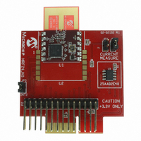
DAUGHTER BOARD PICTAIL PLUS
Manufacturer
Microchip Technology
Type
Transceiver, 802.15.4r
Datasheet
1.AC164134-2.pdf
(24 pages)
Specifications of AC164134-1
Frequency
2.4GHz
Silicon Manufacturer
Microchip
Core Architecture
PIC
Core Sub-architecture
PIC18
Silicon Core Number
PIC18F
Kit Contents
Board
Rohs Compliant
No
Lead Free Status / RoHS Status
Lead free / RoHS Compliant
For Use With/related Products
MRF24J40
Lead Free Status / Rohs Status
Lead free / RoHS Compliant
For Use With
Explorer 16 Development Boards
Lead Free Status / RoHS Status
Lead free / RoHS Compliant, Lead free / RoHS Compliant
Available stocks
Company
Part Number
Manufacturer
Quantity
Price
Company:

Part Number:
AC164134-1
Manufacturer:
Microchip Technology
Quantity:
135


2.1
2.2
2009 Microchip Technology Inc.
INTRODUCTION
PLUGGING INTO THE PIC18 EXPLORER BOARD
The MRF24J40MA/MB PICtail/PICtail Plus Daughter Board can be plugged into multi-
ple Microchip Technology demonstration and development boards. This allows the
developer to choose the microcontroller that best suits the customer’s development
environment.
The PICtail connector right angle header, P2, can plug into 8-bit demonstration and
development boards, such as the PIC18 Explorer Board (DM183032). The PICtail Plus
card edge connector, P1, can plug into Explorer 16 Development Board (DM240001).
This chapter shows how the daughter board is plugged into the PIC18 Explorer and
Explorer 16 Development Boards.
The MRF24J40MA/MB PICtail/PICtail Plus Daughter Board can be plugged into the
PIC18 Explorer Board PICtail connector, J3, as shown in Figure 2-1. Make sure to align
pin 1 to RE2 as shown.
2.2.1
On the PIC18 Explorer Board, push button switch S2 is normally connected to I/O port
pin RA5. RA5 is not a change on interrupt or external interrupt capable I/O pin. Jum-
pering JP3 with a shunt allows the connection of RA5 to RB2/INT2 to allow push button
switch S2 to trigger an interrupt. Keep in mind that RB2 also connects to pin 10 (input)
of U6 (RS232 level shifter) which is a Clear-to-Send (CTS) signal on P2 pin 8 (DE9
receptacle).
Ensure that the PIC18F87J11 PIM is plugged into the PIC18 Explorer Board. This
sets the system V
PICtail/PICtail Plus Daughter Board.
Chapter 2. Getting Started
Configuring Push Button Switch S2 to RB2/INT2
DD
MRF24J40MA/MB PICtail™/PICtail
voltage to 3.3 volts, which is required by the MRF24J40MA/MB
PLUS DAUGHTER BOARD
CAUTION
USER’S GUIDE
DS51867A-page 15
Related parts for AC164134-1
Image
Part Number
Description
Manufacturer
Datasheet
Request
R

Part Number:
Description:
Fuses 16A 415V AC/250V DC
Manufacturer:
Apex Tool Group (Formerly Cooper Tools)

Part Number:
Description:
Manufacturer:
Microchip Technology Inc.
Datasheet:
Part Number:
Description:
Manufacturer:
Microchip Technology Inc.
Datasheet:
Part Number:
Description:
Manufacturer:
Microchip Technology Inc.
Datasheet:
Part Number:
Description:
Manufacturer:
Microchip Technology Inc.
Datasheet:
Part Number:
Description:
Manufacturer:
Microchip Technology Inc.
Datasheet:
Part Number:
Description:
Manufacturer:
Microchip Technology Inc.
Datasheet:
Part Number:
Description:
Manufacturer:
Microchip Technology Inc.
Datasheet:
Part Number:
Description:
Manufacturer:
Microchip Technology Inc.
Datasheet: