EVAL-418-KEY5 Linx Technologies Inc, EVAL-418-KEY5 Datasheet - Page 3
EVAL-418-KEY5
Manufacturer Part Number
EVAL-418-KEY5
Description
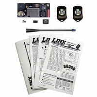
SYSTEM KEYFOB EVAL 418MHZ 5BTTN
Manufacturer
Linx Technologies Inc
Series
KH2r
Type
Transmitter, Receiverr
Specifications of EVAL-418-KEY5
Frequency
418MHz
Product
RF Development Tools
Maximum Frequency
418 MHz
Supply Voltage (max)
3 V
Lead Free Status / RoHS Status
Contains lead / RoHS non-compliant
For Use With/related Products
KH2 Series RF Modules - 418MHz, Linx OEM Modules
Lead Free Status / Rohs Status
Lead free / RoHS Compliant
Other names
EVAL418KEY5


RANGE TESTING
ABOUT ANTENNAS
Page 4
Several complex mathematical models exist for determining path loss in many
environments. These models vary as the transmitter and receiver are moved
from indoor operation to outdoor operation. Although these models can provide
an estimation of range performance in the field, the most reliable method is to
simply perform range tests using the transmitter and receiver in the intended
operational environment.
Simple range testing can be performed with the transmitter and receiver
evaluation boards. To prepare the board for range testing, ensure that JP3 is
closed on the transmitter board and that the address line DIP switches on both
boards are identically set. Turn on the boards by switching the power switch to
the ON position. Pressing S0 on the transmitter will activate the buzzer on the
receiver board, while S1 activates the LED. Placing a jumper across JP1 or JP2
will cause the transmitter to continiously transmit. This will allow the designer to
turn on the transmitter and walk with the receiver.
As you near the maximum range of the link in your area, it is not uncommon for
the signal to cut in and out as you move. This is normal and can result from other
interfering sources or fluctuating signal levels due to multipath effects. This
results in cancellation of the transmitted signal as direct and reflected signals
arrive at the receiver at differing times and phases. The areas in which this
occurs are commonly called “nulls” and simply walking a little farther will usually
restore the signal.
Since the evaluation boards are intended for use by design engineers, they are
not FCC certified. The transmitter has been set to approximate legal limits by
resistor R1 so that the range test results will approximate the results from a well-
designed, certified product. For applications where Part 15 limits are not
applicable or output levels can be legally raised due to protocol duty cycle, R1
can be changed according to the graph on Page 3 of the KH Series Transmitter
Data Guide.
To achieve maximum range, keep objects such as your hand away from the
antenna and ensure that the antenna on the transmitter has a clear and
unobstructed line-of-sight path to the receiver board. Range performance is
determined by many interdependent factors. If the range you are able to achieve
is significantly less than specified by Linx for the products you are testing, then
there is likely a problem with either the board or the ambient RF environment in
which the board is operating. First, check the battery, jumper routing, and
antenna connections. Next, measure the receiver’s RSSI voltage with the
transmitter turned off to determine if ambient interference is present. If this fails
to resolve the issue, please contact Linx technical support.
The choice of antennas is one of the most critical and often overlooked design
considerations. The range, performance, and legality of an RF link are critically
dependent upon the type of antenna employed. Linx offers a variety of antenna
styles that you may wish to consider for your design. Included with your kit is a
Linx CW Series connectorized whip antenna that should be connected prior to
using the kit. Despite the fact that the antenna is not centered on the board’s
ground plane, it exhibits a VSWR of <1.7 and suitably demonstrates the
module’s best practical performance.
USING THE BOARDS AS A DESIGN REFERENCE
IN CLOSING
ONLINE RESOURCES
The basic evaluation boards included in this kit are very simple, yet they illustrate
some important techniques that you may wish to incorporate into your own board
layout. You will observe that the KH mounting pads extend slightly past the edge
of the part. This eases hand assembly and allows for better heat conduction
under the part if rework is necessary. Next, observe the use of a full ground
plane fill on the lower side of the board. This ground plane serves three important
purposes:
First, since a 1/4-wave antenna is employed, the ground plane is critical to serve
as a counterpoise (you may wish to read Application Note AN-00500 Antennas:
Design, Application, and Performance for additional details on how a ground
plane affects antenna function).
Second, a ground plane will suppress the transfer of noise between stages of a
product, as well as unintentional radiation of noise into free space.
Third, a ground plane allows for the implementation of a microstrip feed to the
antenna. The term microstrip refers to a PCB trace running over a ground plane
that is designed to serve as a 50-ohm transmission line between the module and
the antenna. A microstrip is implemented on this evaluation board. If you are
unfamiliar with microstrip calculations, you may wish to refer to the KH Series
data guides or the calculator available on our website.
Here at Linx, “Wireless Made Simple” is more than just our motto, it is our
commitment. A commitment to the highest caliber of product, service, and
support. That is why, should you have questions or encounter any difficulties
using the evaluation kit, you’ll be glad to know many resources are available to
assist you. First, check carefully for the obvious, then visit our website at
www.linxtechnologies.com or call 541-471-6256 between 9AM and 4PM Pacific
Time to speak with an application engineer.
Legal Notice
All Linx kits and modules are designed in keeping with high engineering standards;
however, it is the responsibility of the user to ensure that the products are operated in a
legal and appropriate manner. The purchaser understands that legal operation may require
additional permits, approvals, or certifications prior to use, depending on the country of
operation.
If you have questions regarding any Linx product and have Internet access,
make www.linxtechnologies.com your first stop. Our website is organized in an
intuitive format to give you the answers you need. Day or night, the Linx website
gives you instant access to the latest information regarding the products and
services of Linx. It’s all here: manual and software updates, application notes, a
comprehensive knowledgebase, FCC information, and much more. Be sure to
visit often!
Page 5
Related parts for EVAL-418-KEY5
Image
Part Number
Description
Manufacturer
Datasheet
Request
R

Part Number:
Description:
KIT EVAL FOR HHCP 418MHZ XMITTER
Manufacturer:
Linx Technologies Inc
Datasheet:

Part Number:
Description:
KIT BASIC EVAL 418MHZ LC SERIES
Manufacturer:
Linx Technologies Inc

Part Number:
Description:
KIT BASIC EVAL 418MHZ LR SERIES
Manufacturer:
Linx Technologies Inc
Datasheet:

Part Number:
Description:
KIT EVAL FOR HHLR 418MHZ XMITTER
Manufacturer:
Linx Technologies Inc
Datasheet:

Part Number:
Description:
KIT EVAL FOR LT SERIES 418MHZ
Manufacturer:
Linx Technologies Inc
Datasheet:

Part Number:
Description:
KIT BASIC EVAL 418MHZ KH2 SERIES
Manufacturer:
Linx Technologies Inc
Datasheet:

Part Number:
Description:
KIT BASIC EVAL 418MHZ LC SERIES
Manufacturer:
Linx Technologies Inc
Datasheet:

Part Number:
Description:
RF Modules & Development Tools 3 Button Keyfob Eval Sys 418MHz
Manufacturer:
Linx Technologies Inc
Datasheet:
Part Number:
Description:
RF Modules & Development Tools 1 Button Keyfob Eval Sys 418MHz
Manufacturer:
Linx Technologies Inc
Datasheet:
Part Number:
Description:
RF Modules & Development Tools 2 Button Keyfob Eval Sys 418MHz
Manufacturer:
Linx Technologies Inc
Datasheet:

Part Number:
Description:
MODULE USB LOW SPEED
Manufacturer:
Linx Technologies Inc
Datasheet:

Part Number:
Description:
IC TRANSCODER MT BI-DIR 20-SSOP
Manufacturer:
Linx Technologies Inc
Datasheet:

Part Number:
Description:
IC ENCODER LOW SECURITY 8DIP
Manufacturer:
Linx Technologies Inc
Datasheet:

Part Number:
Description:
IC DECODER MS SERIES 20-SSOP
Manufacturer:
Linx Technologies Inc
Datasheet:
Part Number:
Description:
IC ENCODER MS SERIES 20-SSOP
Manufacturer:
Linx Technologies Inc
Datasheet: